Fab Academy Weekly Reports
w1 | w2 | w3 | w4 | w5 | w6 | w7 |
w8 | w9 | w11-w13 | w14 | w15 | w16 | w17 | w18 | Go back
W1 - Principles and practices
The weekly task:
- Update your webpage with: A new section for FabAcademy, a post/page for each topic and a post/page for each Challenge
- Send a profile picture from you or anything represents yourself
- Browse through the fabacademy web pages of last year MDEF students, select 3 examples of documentation (from weekly tasks) that you find most interesting. Explain why and try to identify the key points.
To make the report I choose
Krzysztof Wronski,
Josefina Nano and
Roger Guilemany.
I have chosen these three websites because each one is a little different from the others in terms of presentation, but all three have in common that weekly separation, and not only thematic. As well as a chronological order. This makes the process of creation and personal development much more understandable
Krzysztof tells very well what he is working on and how he develops it, also his thoughts. As does Roger, who in a very honest way his hypotheses, facts and conclusions. Unlike Josefina, he arranges each week by Facts, Feelings, Findings and Future, making the work of reflection much more schematic, and as a consequence, practical.
Reflection
During the course of Designing for the Next Billion Seconds we were asked < WTF is internet? >, to which I responded:
It’s about a global connection of computers.
A billions of connections where you can find everything, as an implication of something.
I will say it is the algebraic image of computers in our lives, but maybe in the future it will be the metaverse.
A few years ago I thought about it. I realised that we systematically search the internet for what we want to know. So in my opinion, for humans, it's not just a way to connect, it's a way to escape and sometimes to reconnect with reality or to create other realities.
Also few years ago I made this video because of the idea that internet has become everything in our education system.
W2 - Computer-aided design
The weekly task:
- Design and create a 3d model with some relation to each person’s research project. The result must be uploaded to the website in a rendered format.
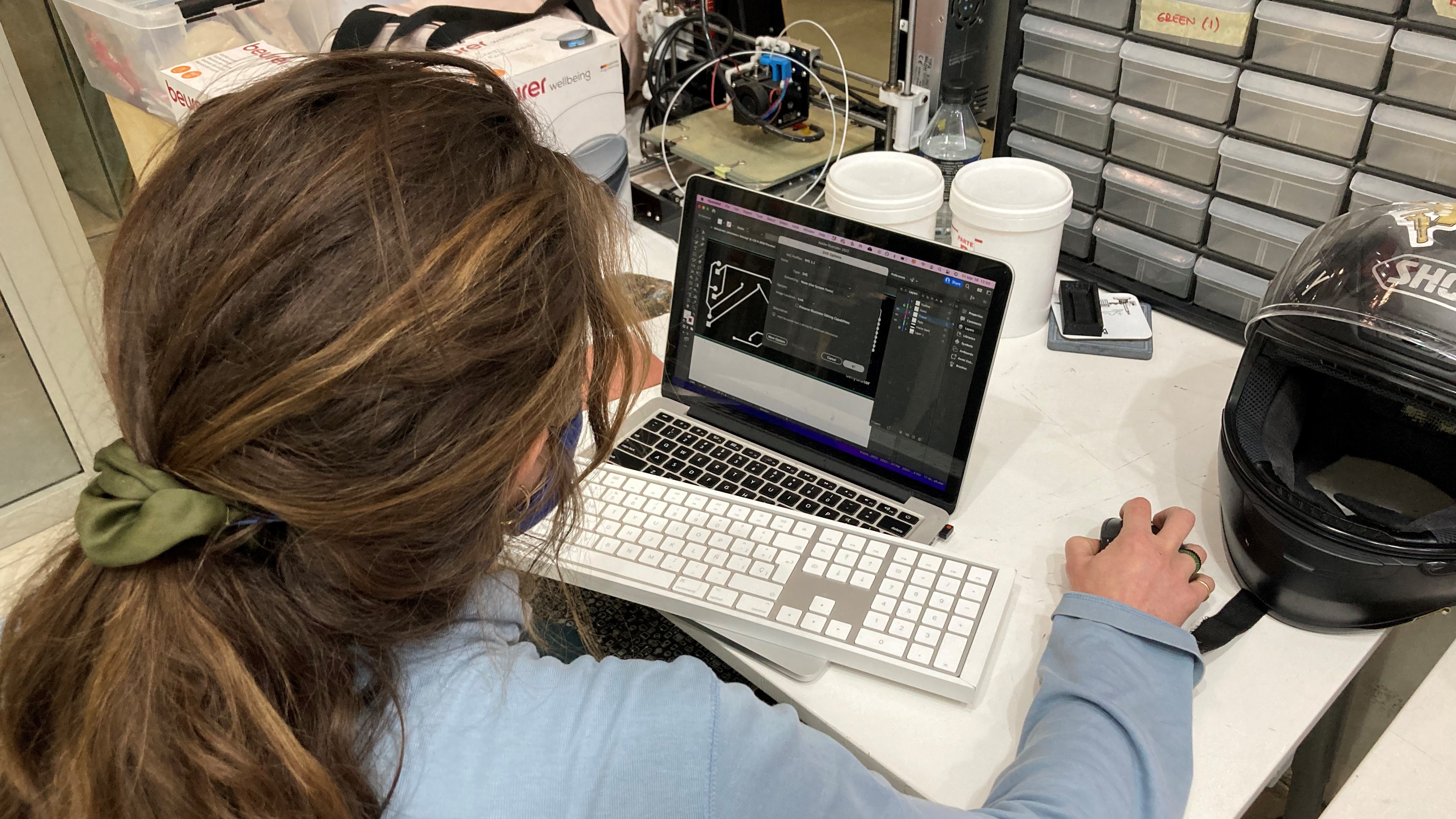
- Setting up context over the render of the 3D model using some 2D design software, the accounted context could be a poster that combines the render as collage or other 2D or 3D tools vectorial or raster compositions as you wish There should be some vectorial and raster drawings on the render.The modeling tools of use are completely open to your skills but we encourage you test softwares that you never used.”
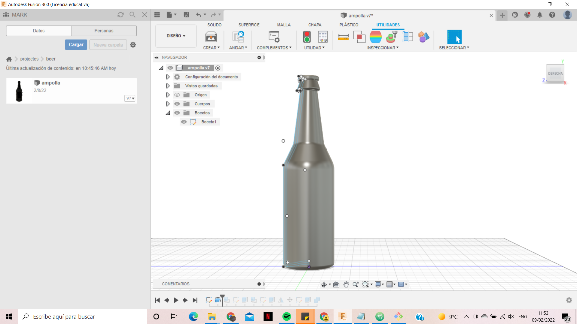
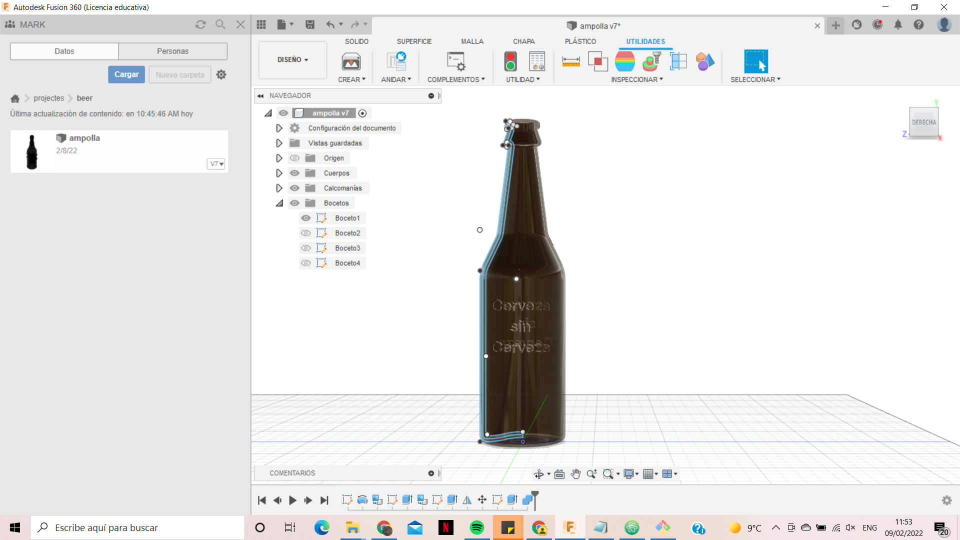
For the 3D model I wanted to try with Rhino, because I already control Fusion, SolidEdge and NX. Also, I thought about Blender, but I see more future working with Rhino than Blender, as it is also a a software for animation even if you can use as an engineer.
I had some problems with Rhino, so for the next week I will try to work only with Rhino, but for now I did this model with Fusion.
The question of the beer it would be, What happens when we are not what we are suppose to be?
The idea not only came from Magritte, it's also a reflection of the shapes of cotidiant objects. As depending of the cultural, social and political sociology in the time.
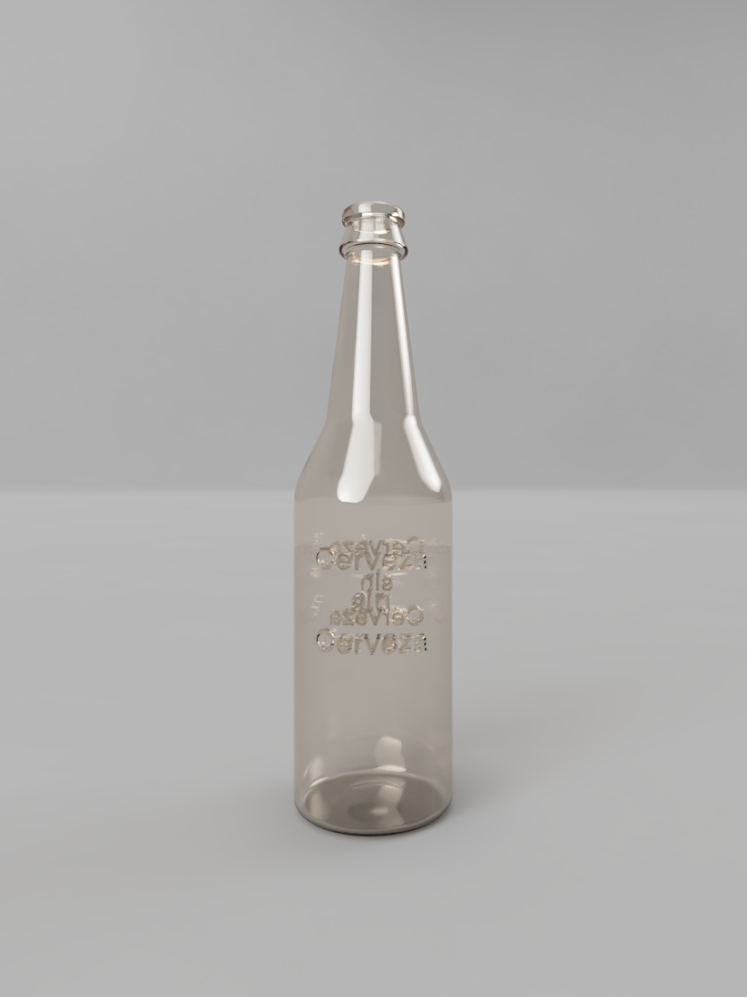
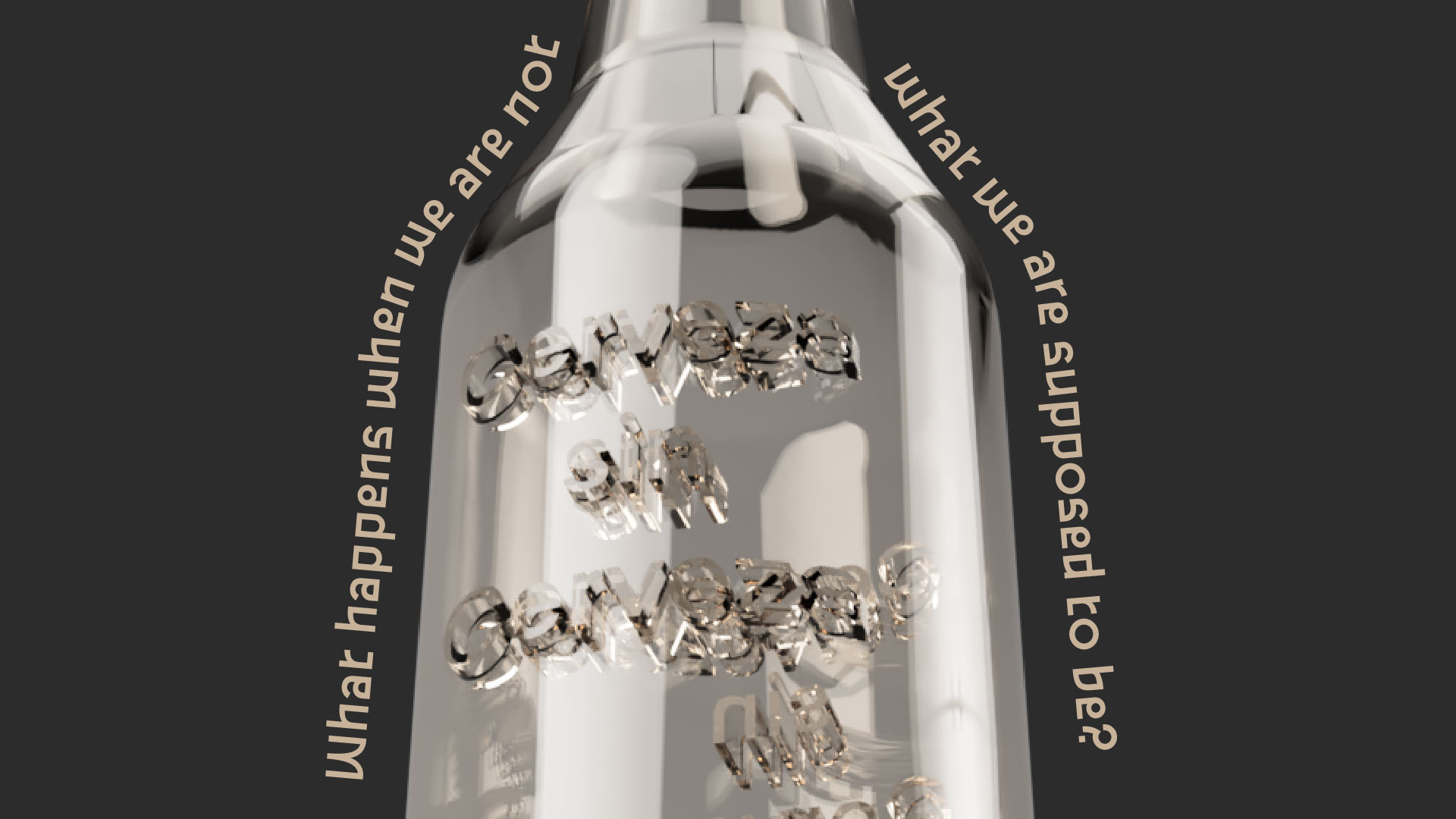
This is the process:

W3 - Computer-controlled cutting
The weekly task:
- Create a small object using parametric design tools. The object should be assembled in a press-fit way (no use of glue, screws etc).
- Complete the Machine test with the 100% of the score
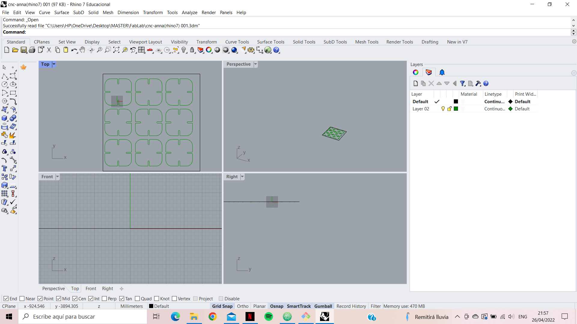
As you might expect, I had not used the laser cutter until I joined this master. Therefore, this is all new to me. As I said I forced myself to do the following task in rhino, to learn it. First I made a design of a piece of furniture as an easel in order to be able to engrave working processes from above. But when I finished I realised that the measurements were bigger than the piece of wood I had. So I designed a puzzle, as my focus of work is games and thinking.
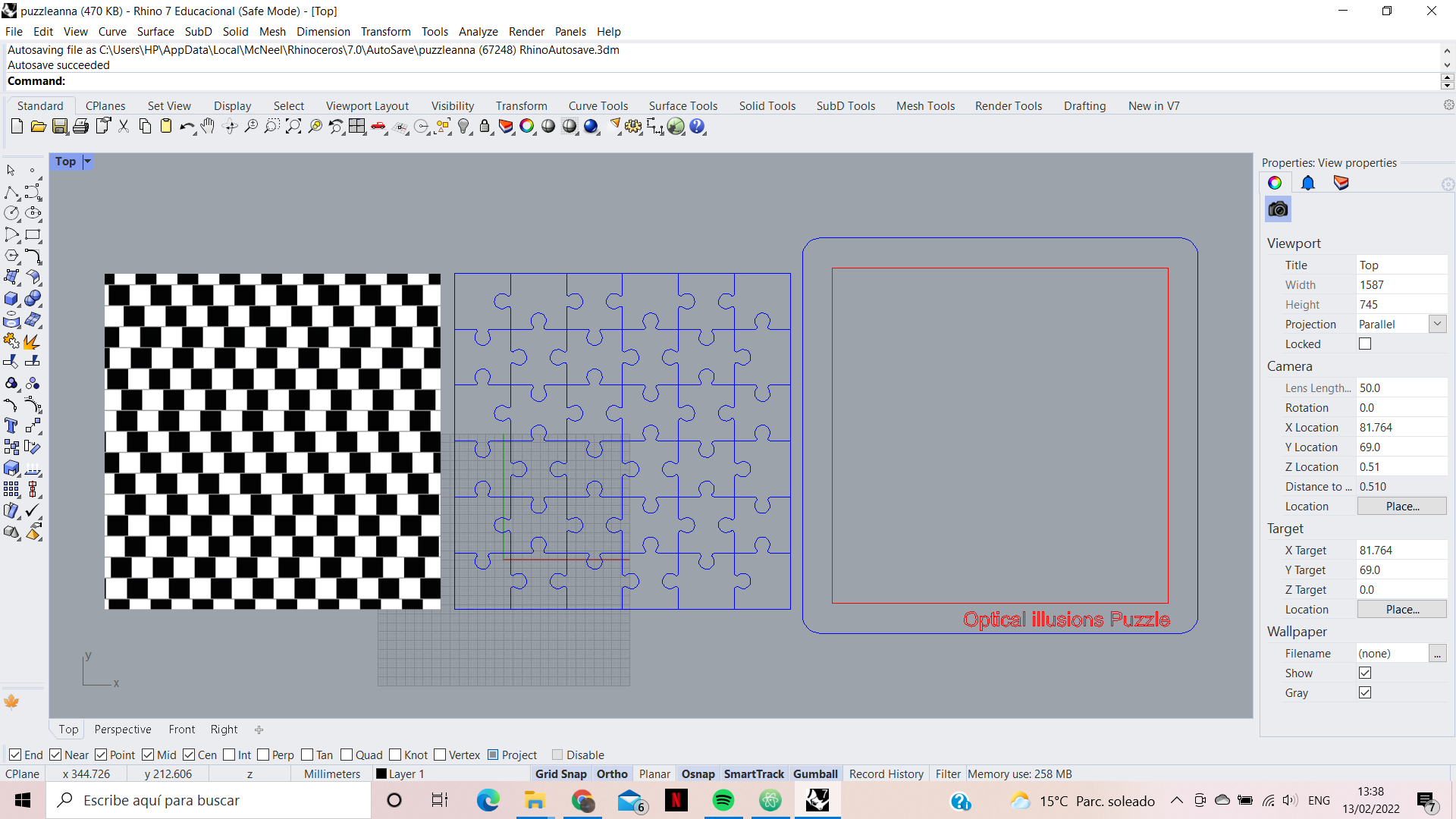
The different types of processes to be implemented must be differentiated in the colours. The red will be engraving, the image and the text will be rastering as High, while the blue will be cutting. If cutting is done before engraving, the piece can move and become misaligned with the original design. Therefore the engraving will be done first and then the cut.
When opening the document in the rhino 5 of the computer connected to the laser, it only allows to choose the engraving or cutting mode, so even if it read the image as engraving, it did not transfer the information well. What we did with Josep then was to separate the file in two. First we printed the engraving without the cut. And then we printed the cut without the engraving. Thanks to the machine remembering the starting point, and obviously we didn't move the board.
MDF 3mm:
- Engrave - Raster : P(80) S(100) Hz(1000)
- Cut : P(55) S(0.5) Hz(1000)

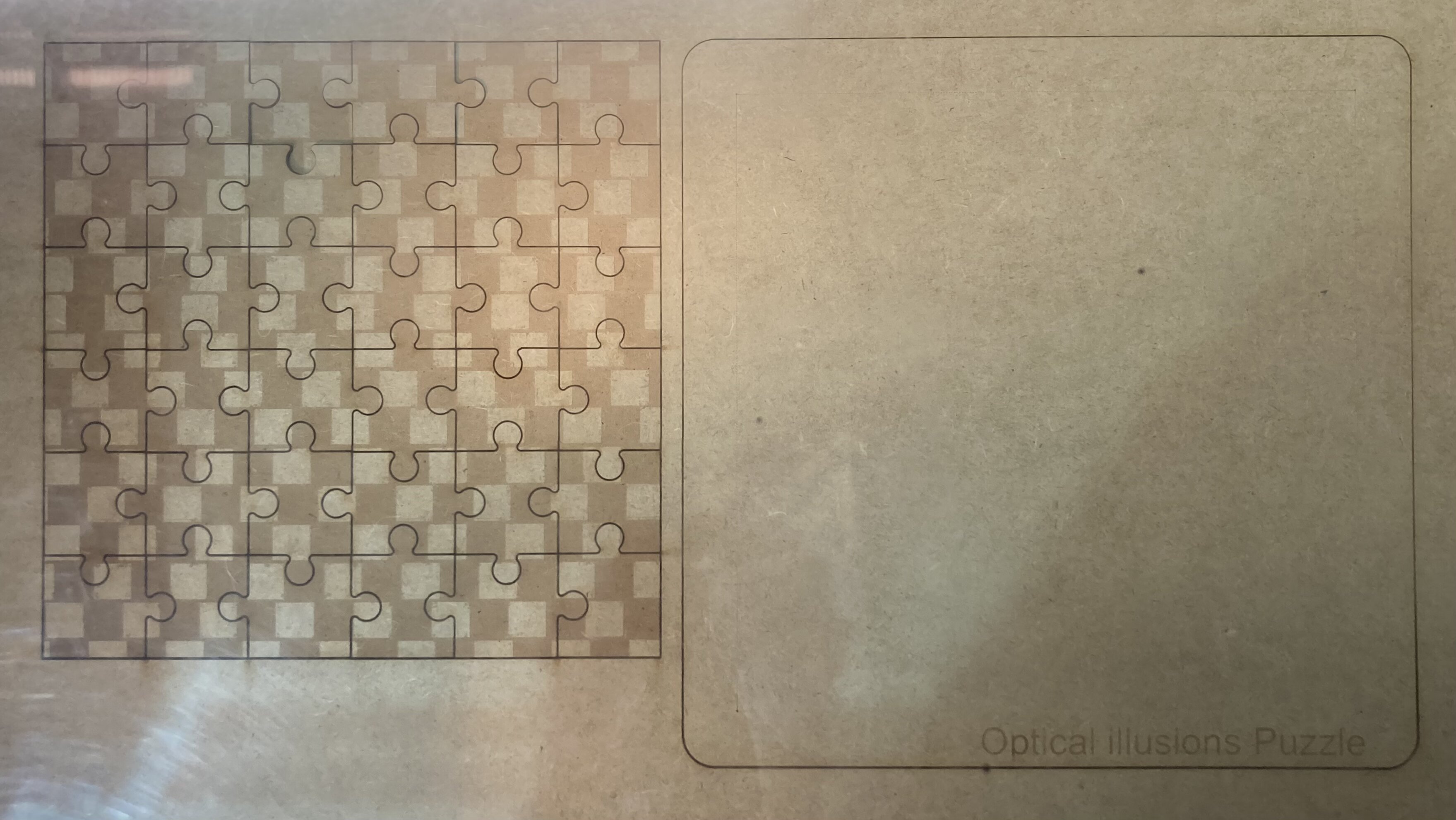
I had some trouble separating some pieces because apparently the laser didn't cut the last layer of MDF, but otherwise there was no problem.
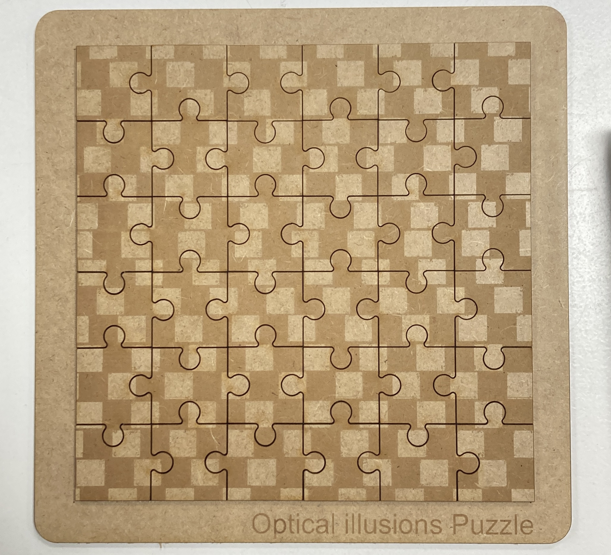
Although it is a great process of creation, it is obviously not made for a mass production process. For small parts it is perfect, but once you start working with large and detailed parts, you lose a lot of time. As well as the energy consumption and toxic fumes it produces. But in the end it is an essential tool for producing details.
I encourage you to create a new puzzle, personify it by changing the image (remember that in black and white the laser engrave much better).
Here you can find the files and download them.
:)
W4 - Electronics production
The weekly task:
- Finish (by pairs) your LED BADGE soldering the smd components and test it(make the led light up with the power supply)
- Tutorial reference
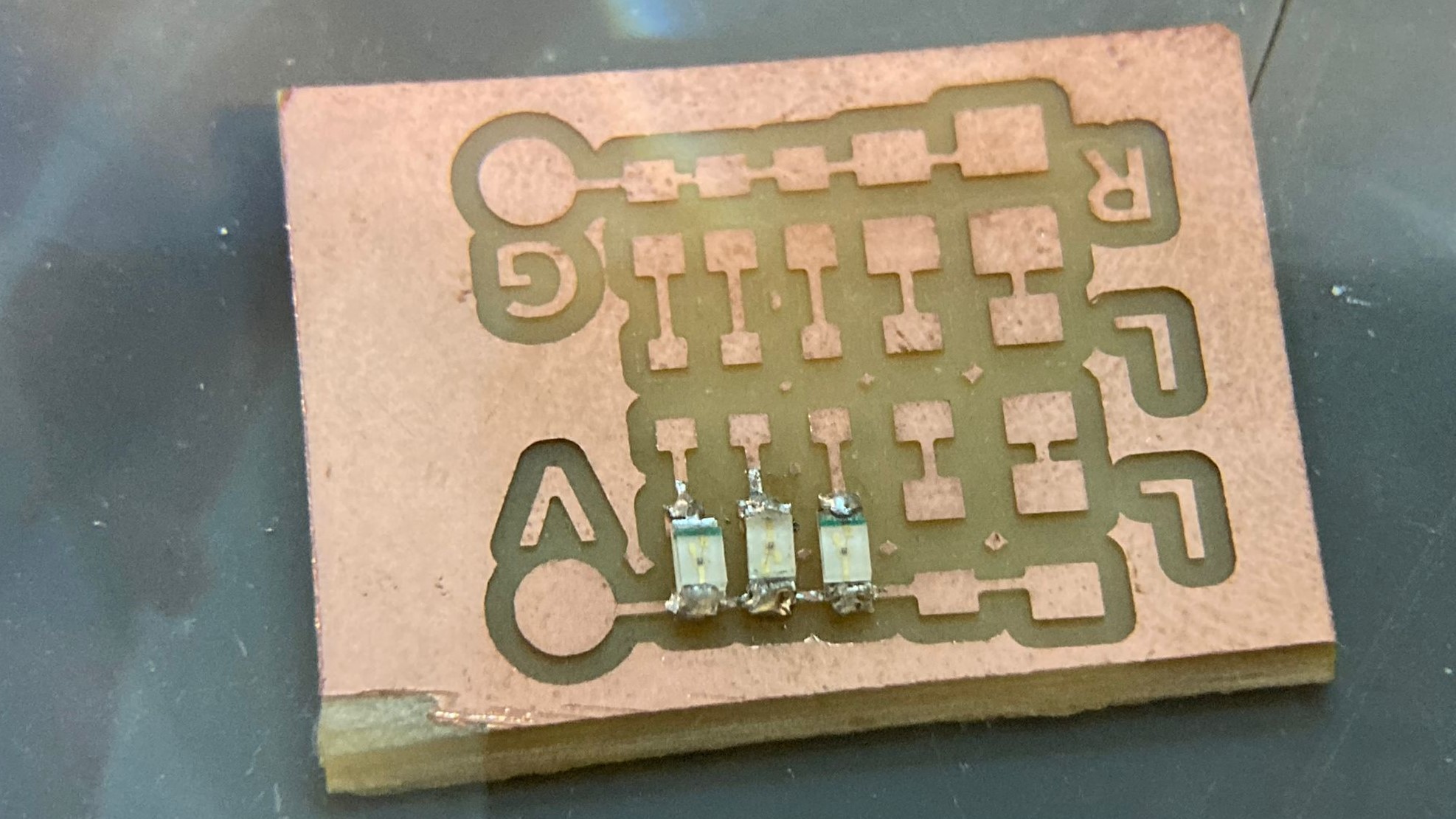
This practice consists of soldering 3 parallel lines 2 of 5 leds in series in each one and 1 line of 5 resistors. Once soldered, make them light up.
In order to weld correctly, you must first heat one of the areas where the element is to be welded with a little welding wire. The element is then positioned and welded on that side. And once we have it well caught, we solder the other side, thus finishing attaching the element to the plate.
With a multimeter we can check that the soldering is correct. By checking if the circuit is closed at each element between the solder joints, so that current is flowing.
By doing these checks I realised that the second LED soldered to the circuit I had put it in the wrong direction. And I noticed that the green line marked the direction of the LED.
I tried to remove the solder with the copper strip by heating it, as Julia explained to me that I could remove the solder wire. But I didn't know how to do it correctly. I thought it would be interesting to see how the leds are connected and see which ones were affected by this error. And this way I could see clearly how the board works.
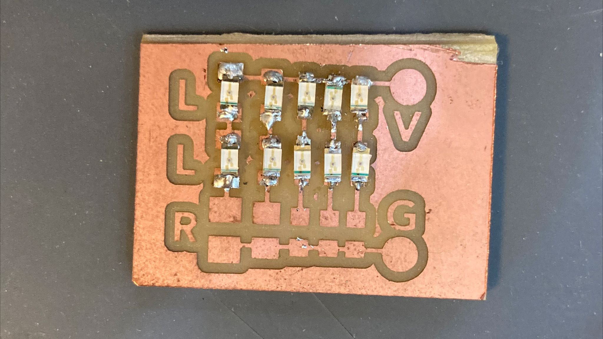
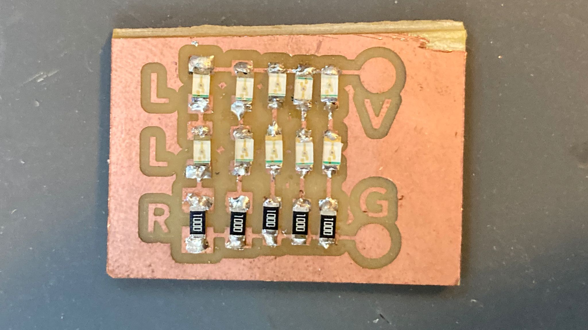
Final Test
This was the result of the board being connected to a 5V supply, having the previous error.
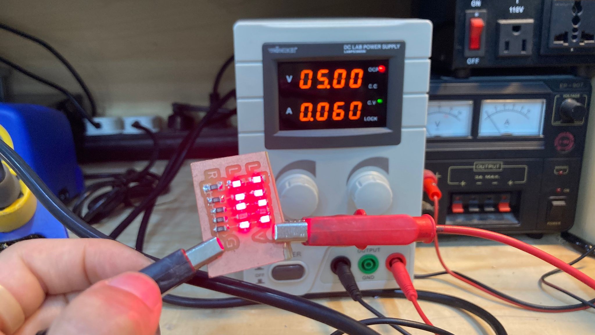
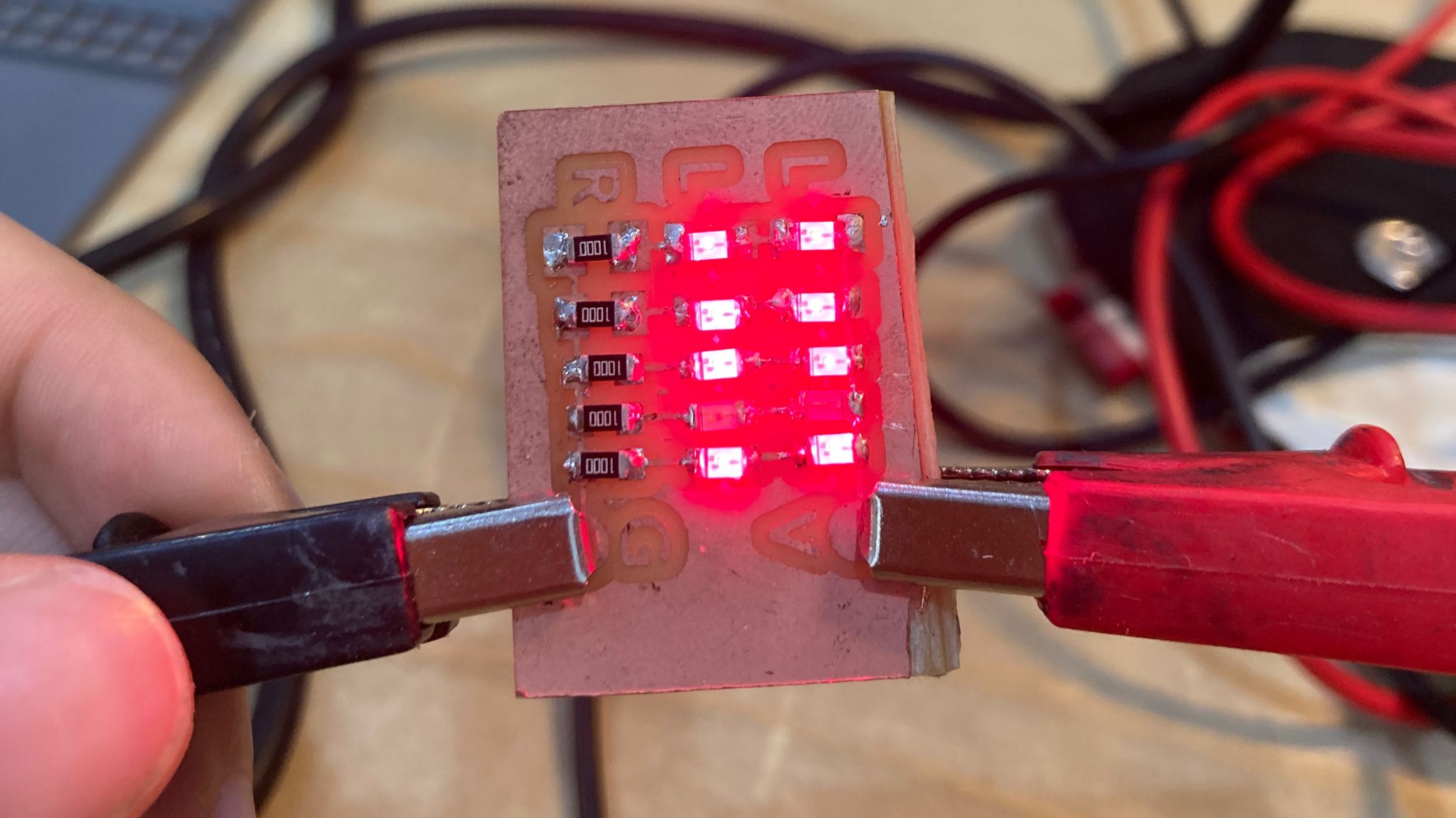
We can see that only the LED that connects parallel to it is affected. And we can see how it is affected in parallel but not in series.
W5 - 3D printing and scanning
The weekly task:
- 3D print an object you have modelled(not something you have downloaded) that could only be made with Additive manufacturing techniques
- Your 3d printed object cannot be bigger than 70x70x70mm or take more than 3 hours
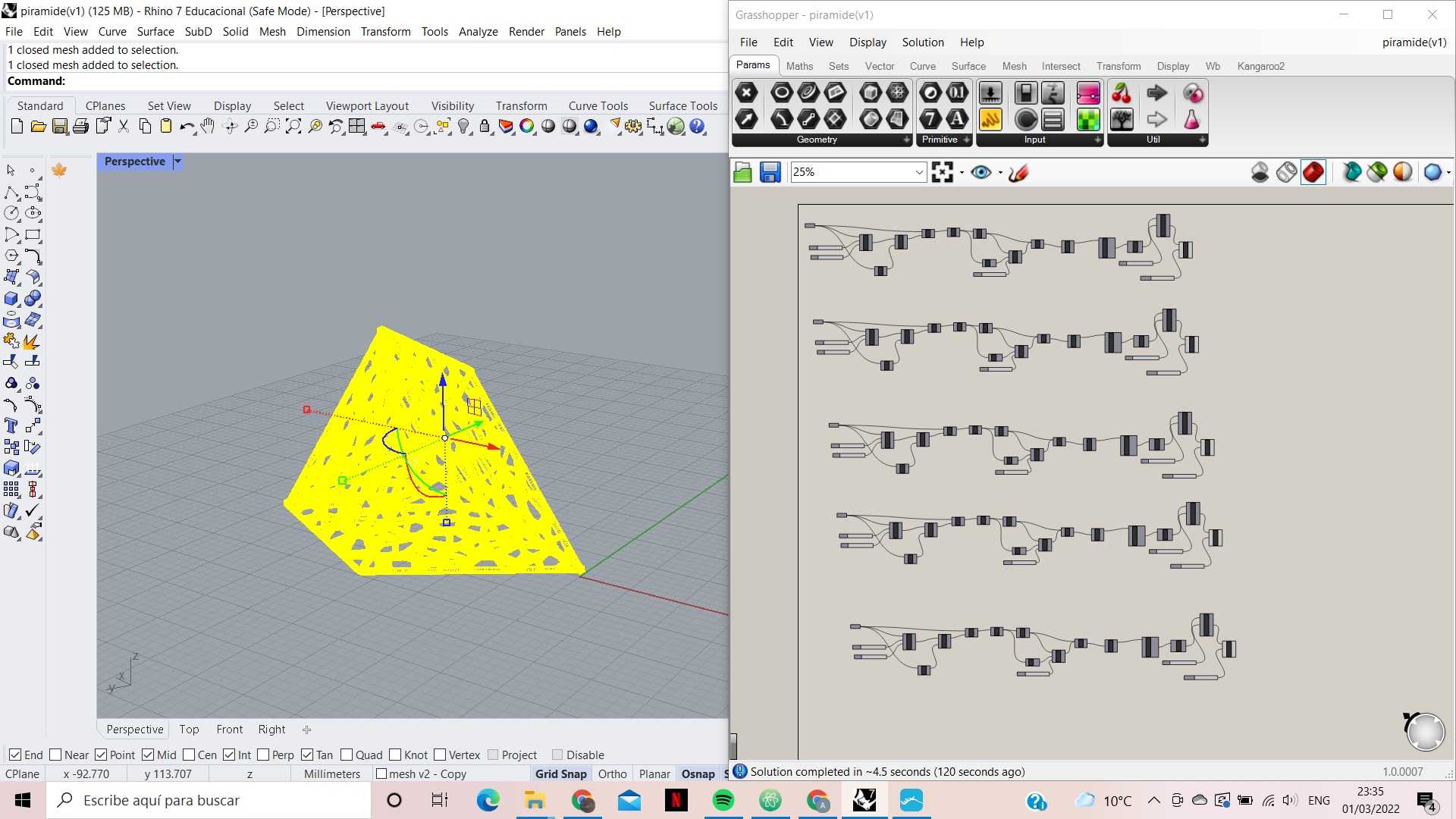
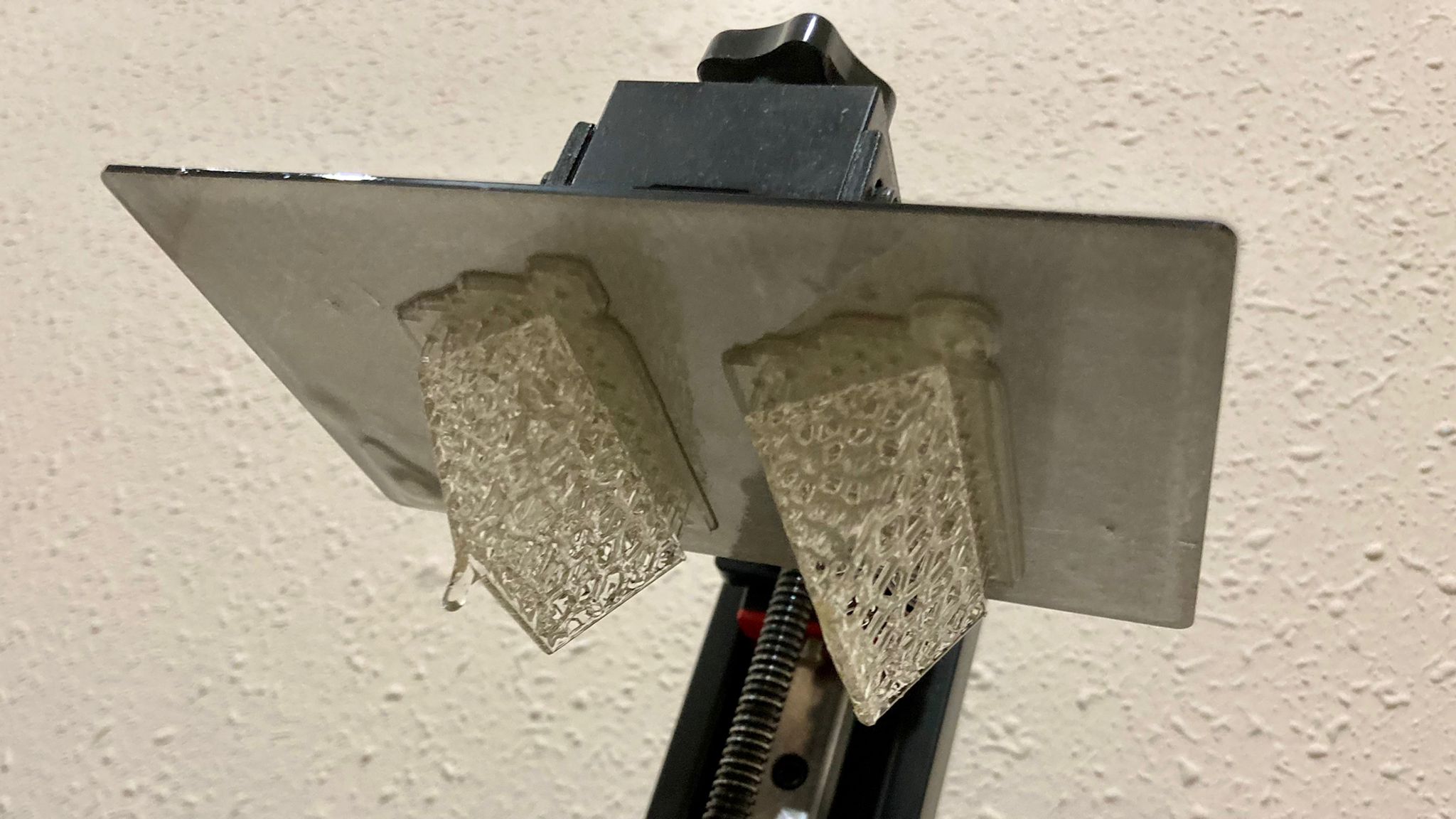
The printer I’ve decided to use to make the part is the creality LD-002H. This printer is resin, in this case Plant-based Elegoo translucent resin has been used. Rhino has been used together with Grasshopper to create the modeling. And the software for the machine has been chitubox.
The main idea of the object I would like to create is a version of the puzzle that contains two identical pieces and creates a pyramid between them. Since geometry is stipulated by the game itself, I would like to play with void and organic shapes.
Process
Since I had never used the GrassHopper tool I have looked for some tutorial to be able to make some dynamic form of my main idea. So I followed the following YouTube tutorial.
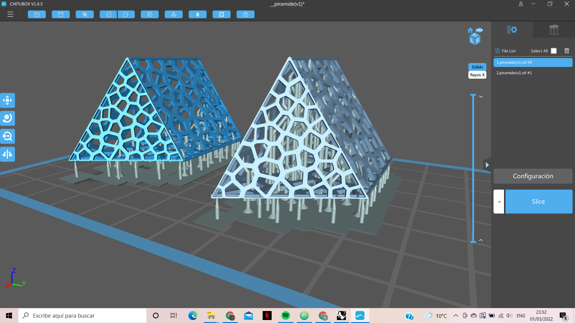
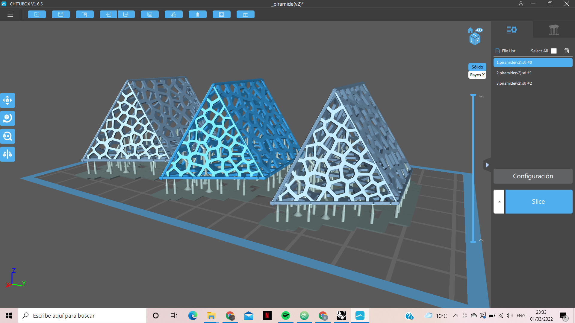
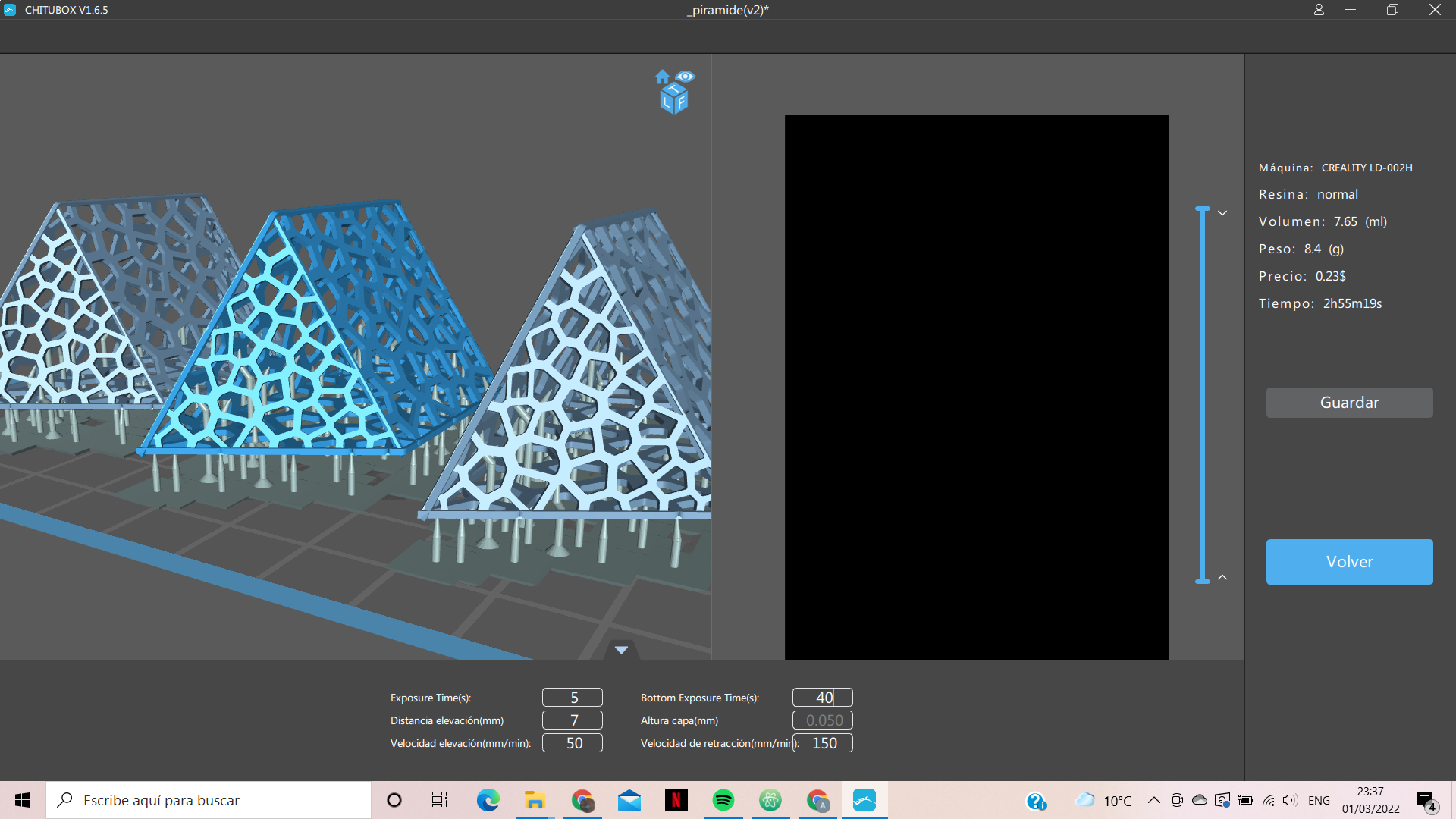
After creating the mesh, it has been saved in stl format and opened the chitubox program. As is the program recommended by the same company Creality, this already contains a library with different resin 3D printers. And since I’ve worked with this program before, it’s already programmed for the machine in question.
The process is basically to scale it as it seems perfect. Because it’s a design that only depends on the two pieces being the same, we don’t care so much about the exact size. And adding brackets to the piece. Being a piece with many holes and angles not very well if the machine will be able to correctly capture the shape, so and to facilitate its extraction without damaging the design, we must add supports (very rarely in resin is not necessary the supports).
From past experiences and as you can see it is obvious that once printed it will be very difficult to remove the supports. For this reason I have decided to print two parts with different support; one with support made automatically by the machine, and in the other I have manually removed the inner support. In this way we will be able to check if the part really needs the inner supports or not.
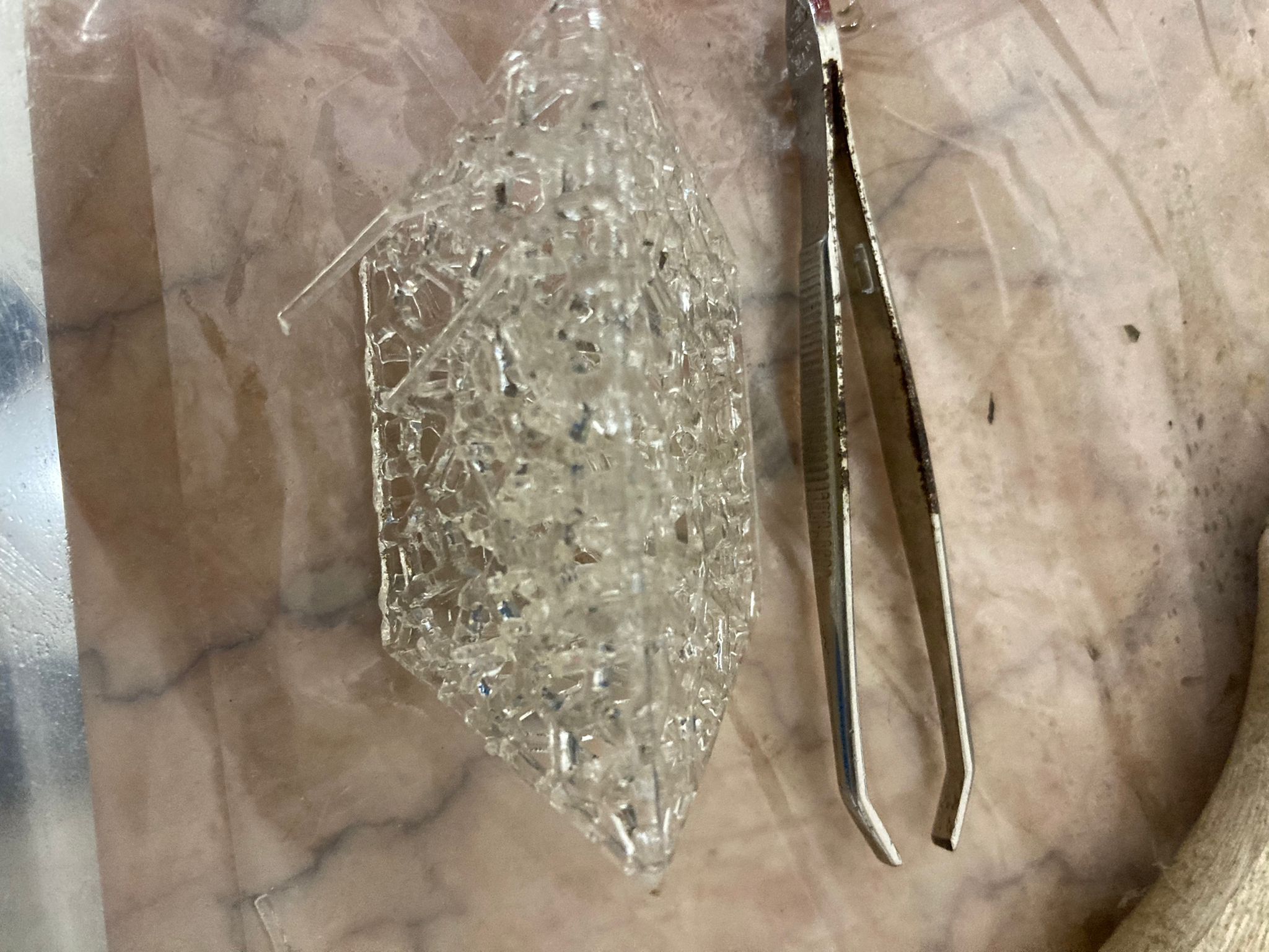
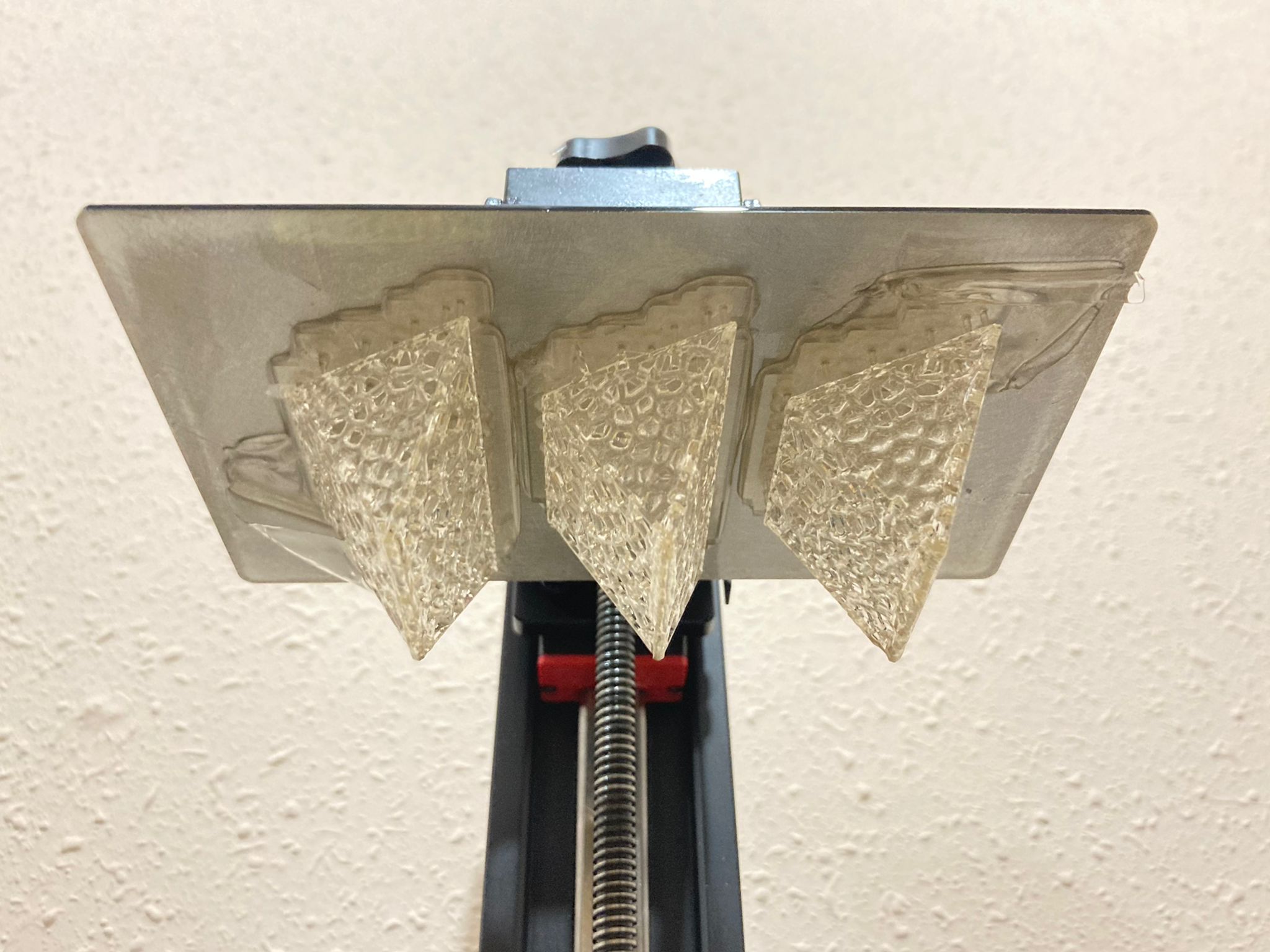
Final object
W6 - Electrincs design
The weekly task:
- Design a PCB board also called breakout-board for your ESP32 HUZZAH 32 microcontrollers ( or other board that you want to use rapberri pi ,etc) that allows you to connect an input (sensor) or an output (actuator) to your commercial board without cables.
- Include the design files in your webpage and explain well the process on how you did it.
\
For this activity we have learned to use kicad to be able to manufacture a pcb board. As Julia wants to create a dehydrator, which I am also very interested in, we have decided to do the activity together. Therefore we have created a PCB board with a temperature sensor and an AC drimmer necessary to change the intensity of the infrareds.
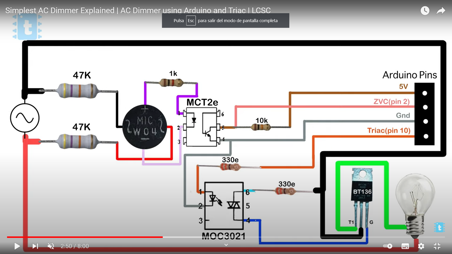
These are the resources we found on the internet. Thanks to this video, we were able to understand how AC drimmer worked and make one. In it you can find the necessary components to manufacture it and all the information of how it works.
During the process we needed Jeremy’s help, who really explained what we needed and how it worked. Also Daphne and Santi to be able to understand well the connections between the elements.
These are the components we need:
Fab Lab library:
- 3x Terminal 2p 5
- 2x Resistor 47k
- Resistor 1k
- Resistor 10k
- 2x Resistor 330e
- Adafruit_Feather_HUZZAH32_ESP32
External resources library:
The Process
This is the scheme that Julia created with Jeremy, to understand what components we needed. Then we find the AC drimmer scheme, which for its high cost we decided to manufacture one instead of buying it, extracted from the previous video.
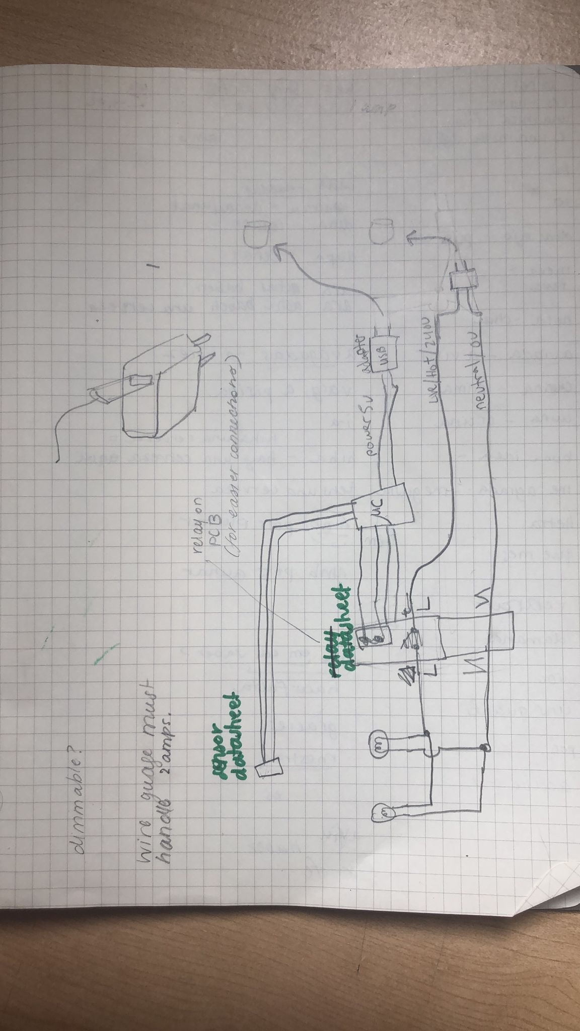
The tricky part is finding the parts needed to produce the dehydrator. After finding both symbols and footprint documents. But once this is all must be installed in the kidCad repository, the symbol in Schematic Layout Editor and the footprint in PCB Layout Editor. It must be understood that the symbology serves to make a diagram of the circuit, in terms of footprint, serves to create the real connections and paths between the components with their real measure.
Once the entire export process is done and we have the idea of the system we can start to create first the document Schematic Layout Editor, then generate netlist and with it open the PCB Layout Editor.
On Jeremy’s recommendation, the high volatge has been separated with the low, to avoid overloads.
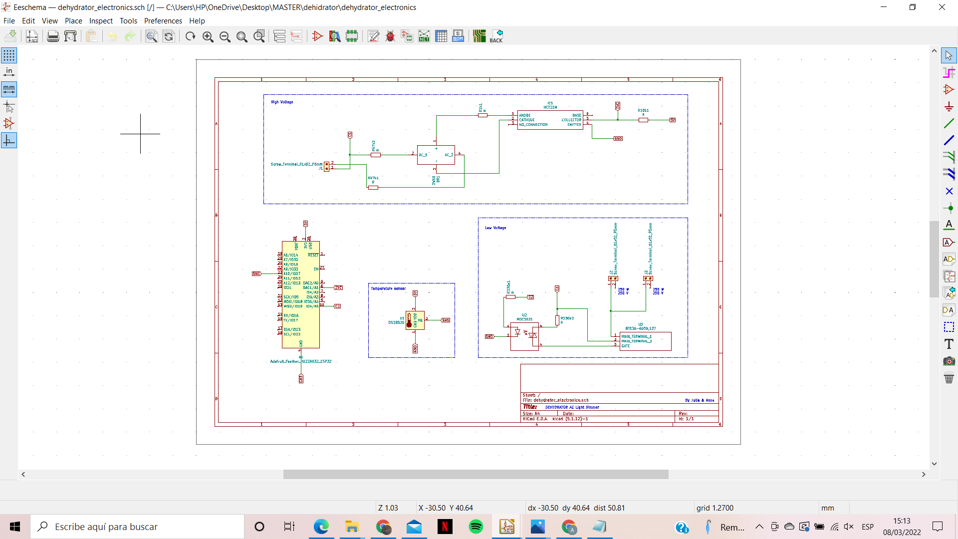
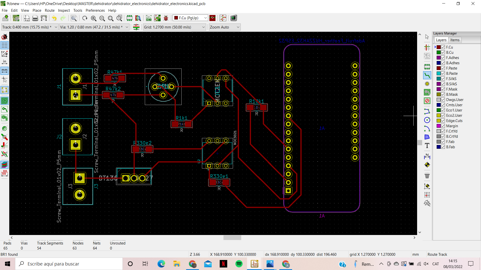
Dehydrator AC drimmer PCB Board
First Prototype
Here you can find all the files of the first prototype.

W7 - Computer-Controlled Machining
The weekly task:
- Design something big IN PAIRS! . You can use up to a maximun of half full board ( that means 1200x1200mm) of the available material per student. 15 mm thick pine plywood boards.
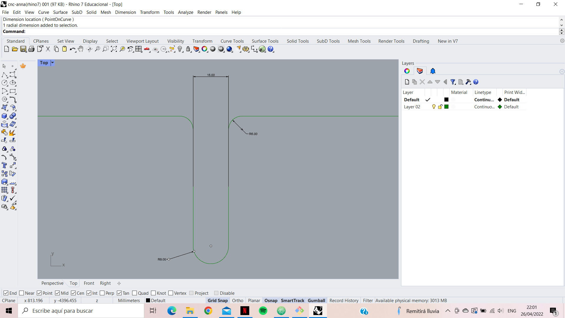
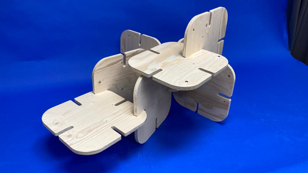
For this practice I have decided to make some modular pieces. The intention is that children can create their own furniture when they play. For this reason it is necessary to fit and unfit the pieces together. So that children can play with them easily, but at the same time they can support the weight of a child. The dimensions of the pieces will be 330 mm, which is the average size of a seat for a 5 year old child.
Next, the thickness of the board (1200 x 1200 mm) has been measured, 14mm. Therefore a tolerance of 2mm has been left for the hole.
After converting the document with Borka and Angel, we started cutting the board together. On the Raptor X-SL Milling Machine it took 2 hours.
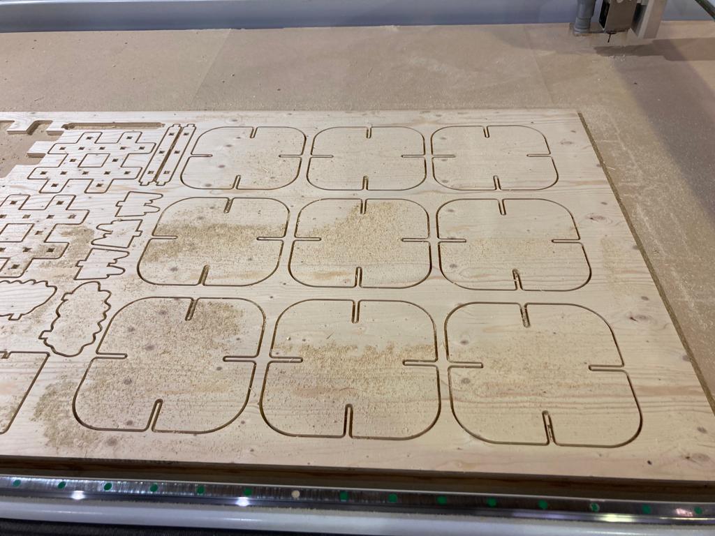
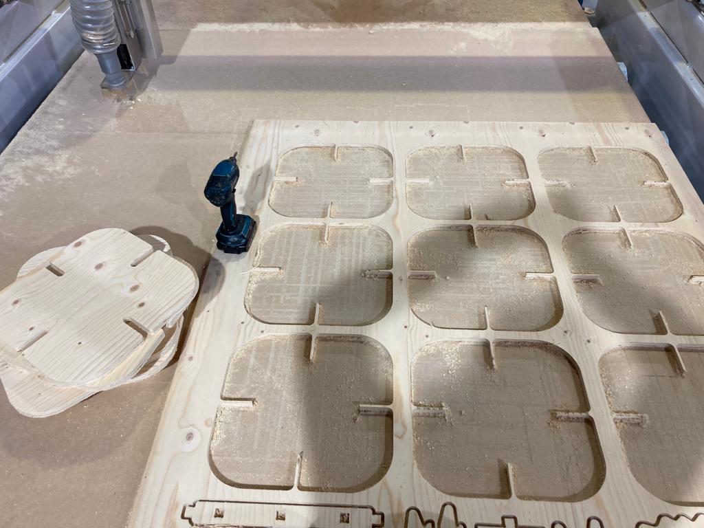
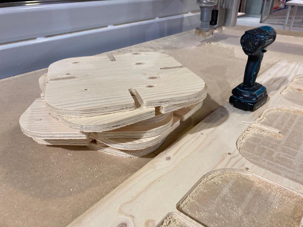
Once the process is finished, we have to remove the screws. And proceed to separate the pieces from the wooden panel. Once done, we can see that the surface finish of the wood, especially in the cut areas, is bad. This is why we must file, so as not to leave any wood chips that could hurt us.
Final Design
W8 - Embedded Programming
The weekly task:
- Use your programmer (HUZZAH32, ESP32 Feather) to program a circuit with a “led and a bottom” to do something
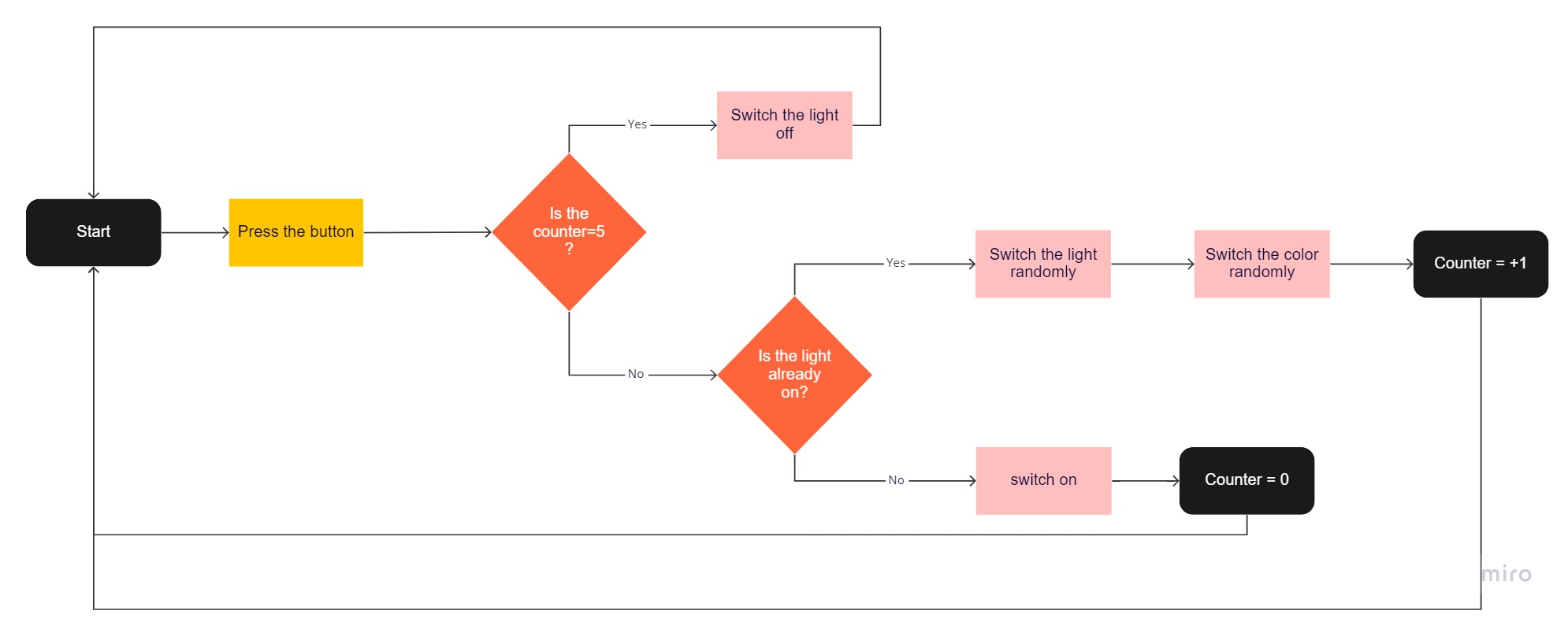
In order to start programming first you must make a flowchart. In this way we can understand the logical functioning that the computer will process. In my case, I want to program the random color change of the LED strip from a button.
This will be programmed with the arduino C++ language, using Arduino IDE, for our ESP32 Feather board.
#include < Adafruit_NeoPixel.h >
#define PIN 15
#define NUMPIXELS 12
Adafruit_NeoPixel pixels = Adafruit_NeoPixel(NUMPIXELS, PIN, NEO_GRB + NEO_KHZ800);
int delayval = 250; // delay for half a second
int counter = 0;
int buttonPin = 3;
void setup()
{
Serial.begin(9600);
pixels.begin(); // This initializes the NeoPixel library.
randomSeed(analogRead(0));
pinMode(buttonPin, INPUT);
}
void loop()
{
if (digitalRead(buttonPin) == HIGH){
counter++;
if (counter == 1){
int led = random(12);
int redNumber = random(255);
}
if (counter = 2){
int led = random(12);
int greenNumber = random(255);
}
if (counter = 3){
int led = random(12);
int blueNumber = random(255);
}
if (counter = 4){
int redNumber = 0;
int greenNumber = 0;
int blueNumber = 0;
counter = 0;
}
}
pixels.setPixelColor(i, pixels.Color(redNumber,greenNumber,blueNumber));
pixels.show(); // This sends the updated pixel color to the hardware.
delay(delayval); // Delay for a period of time (in milliseconds).
}
W9 - Molding and casting
The weekly task:
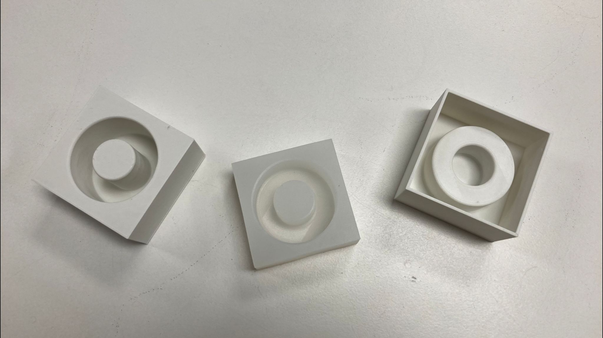
- Make a mold (can be 1 or two sides) HARD-SOFT-HARD . 3DPRINT- CAST SILICONE- CAST SOMETHING INSIDE
- You can use biomaterials to substitute the silicone or the final cast.
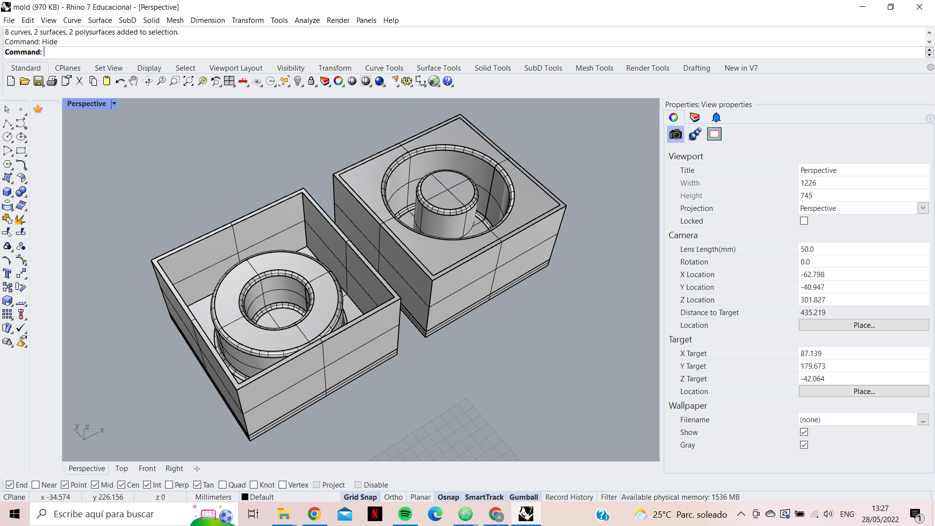
The aim of this activity is to investigate the manufacturing processes of the biomaterial agar-agar. To this end, I have decided to create two active and two passive moulds in 3D printing. The passive one will be tested with the bioplastic to check if a rigid 3D filament mould can be used for its manufacture. While with the active one we will make another soft resin mould where we will test the same. Finally we will check the results with the 3D printing mould.
Process
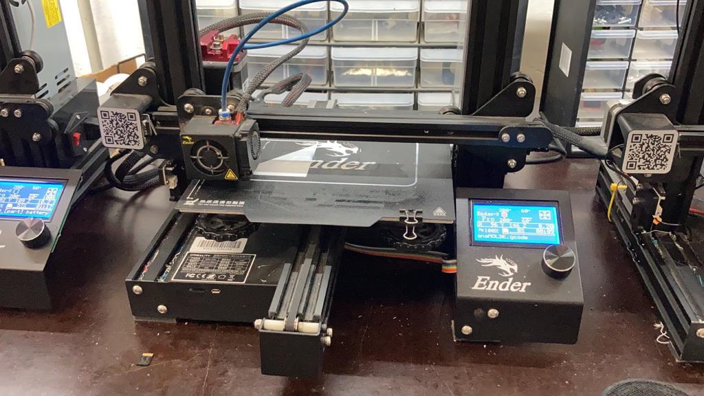
First the two moulds have been designed in Rhino. Then they were left to print overnight on the Ender printer.
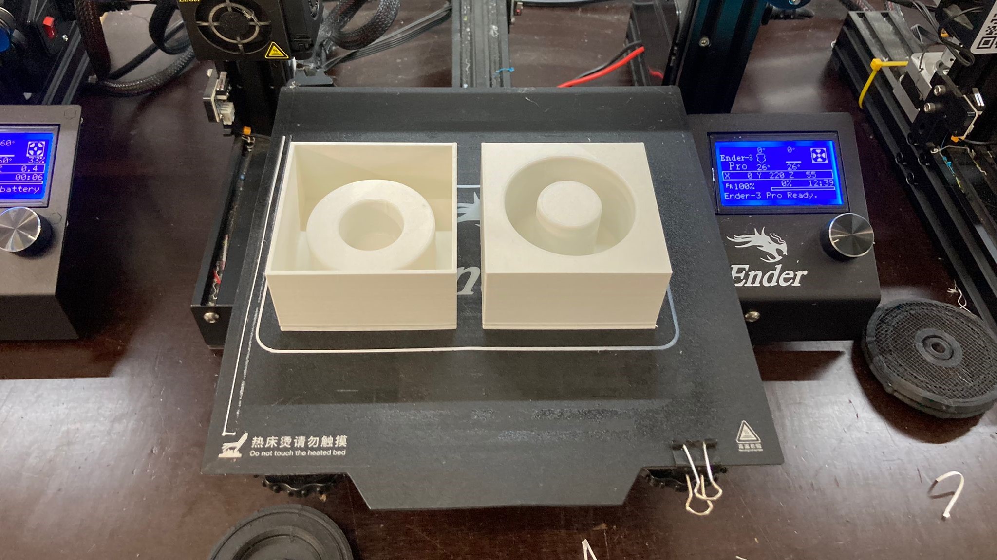
Passive mold
Having the mould in 3D we simply have to apply the recipe, which is based on:
- 4g Agar-agar
- 15mk Glycerin
- 80ml Water
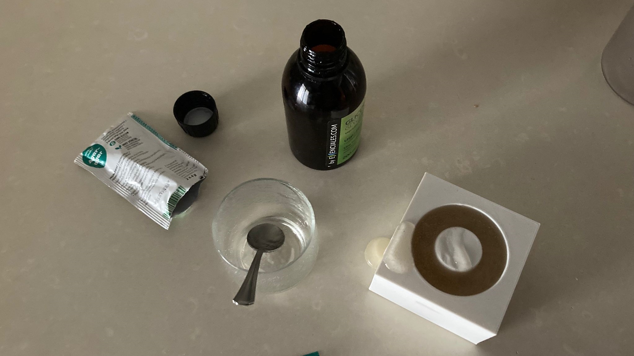
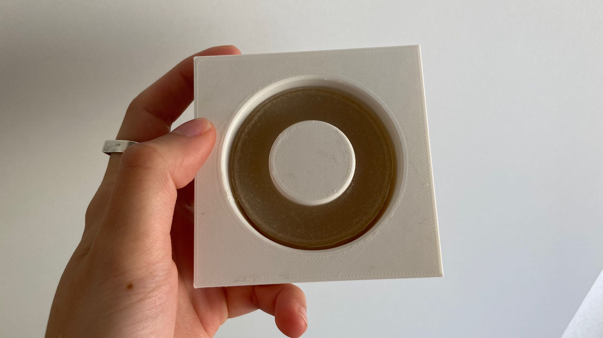
It should be left to stand for at least 3 days in the mould, then removed and left to stand for 5 days.
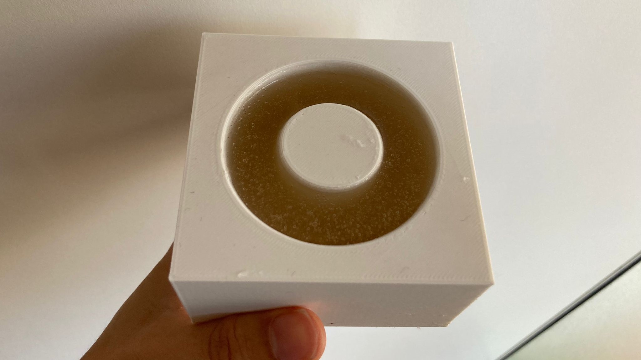
Passive mold Final
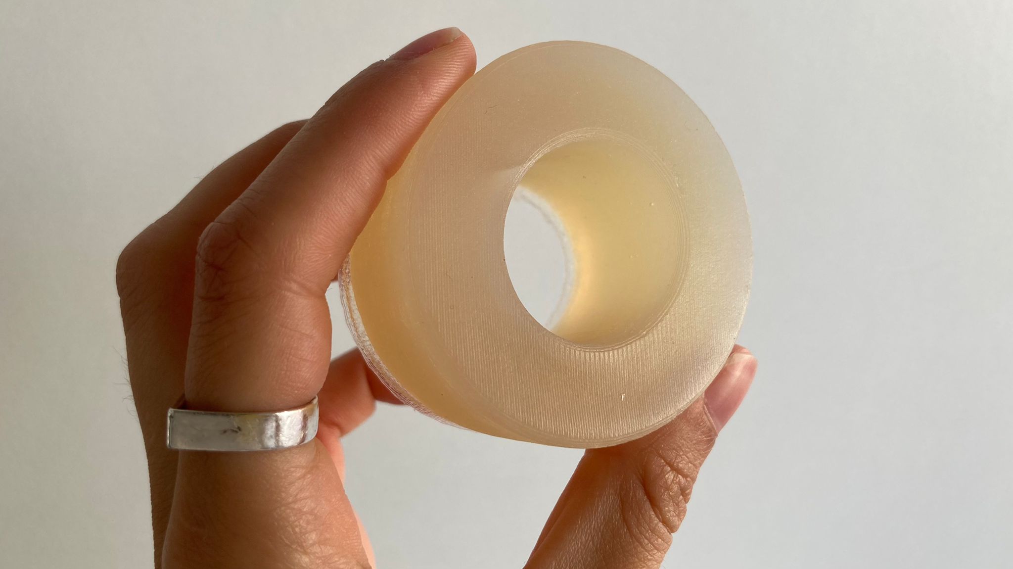
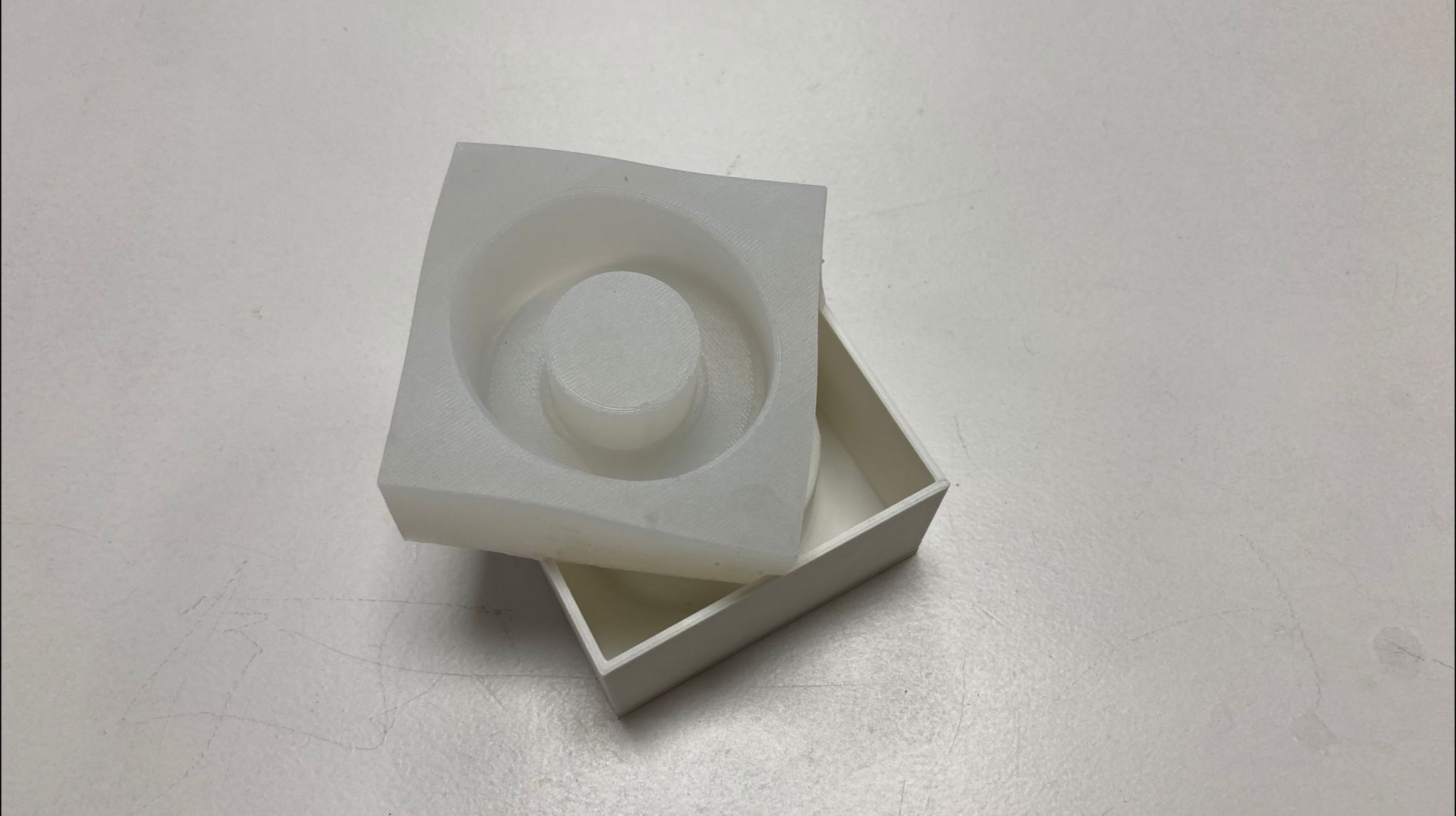
Active mold
In this case we will use soft silicone. This way the proportion is 1/1. And it is much easier to make. Gloves and gown must be worn when dealing with the resin. As there were three of us who needed to make moulds, we decided to do it together.
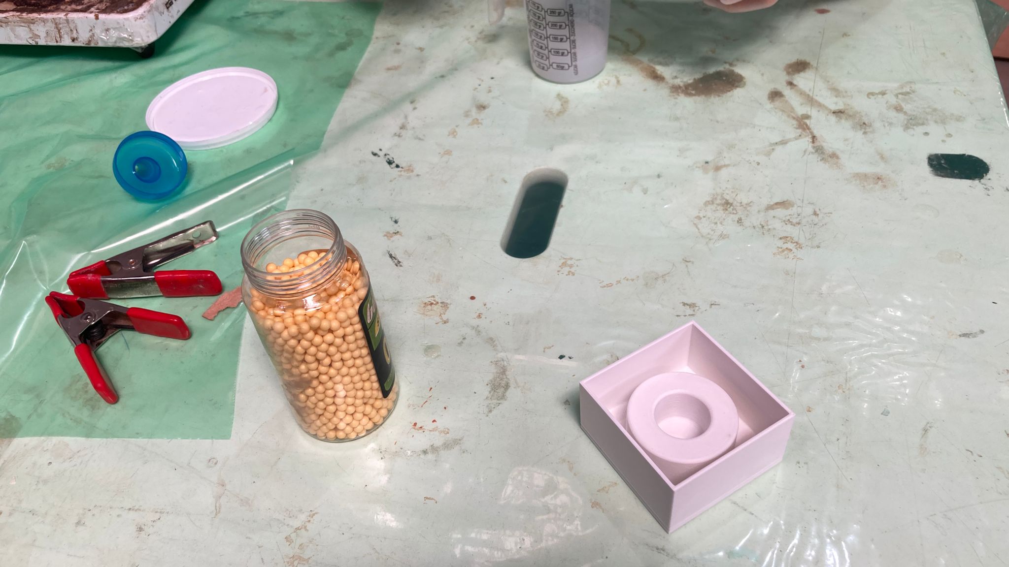
First we calculate the volume we need, by putting the frills inside the 3D base and then measuring it. In my case I needed approximately 130ml. But as we were two more people we made a mixture of approximately 200ml in total.
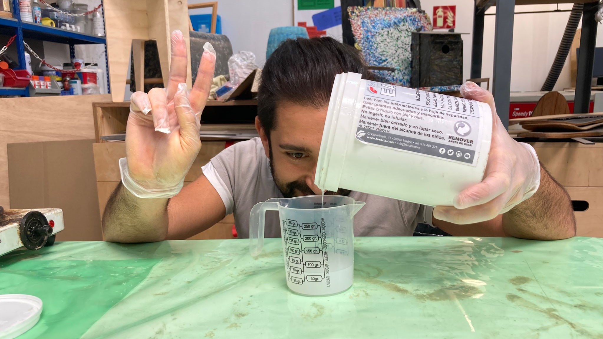
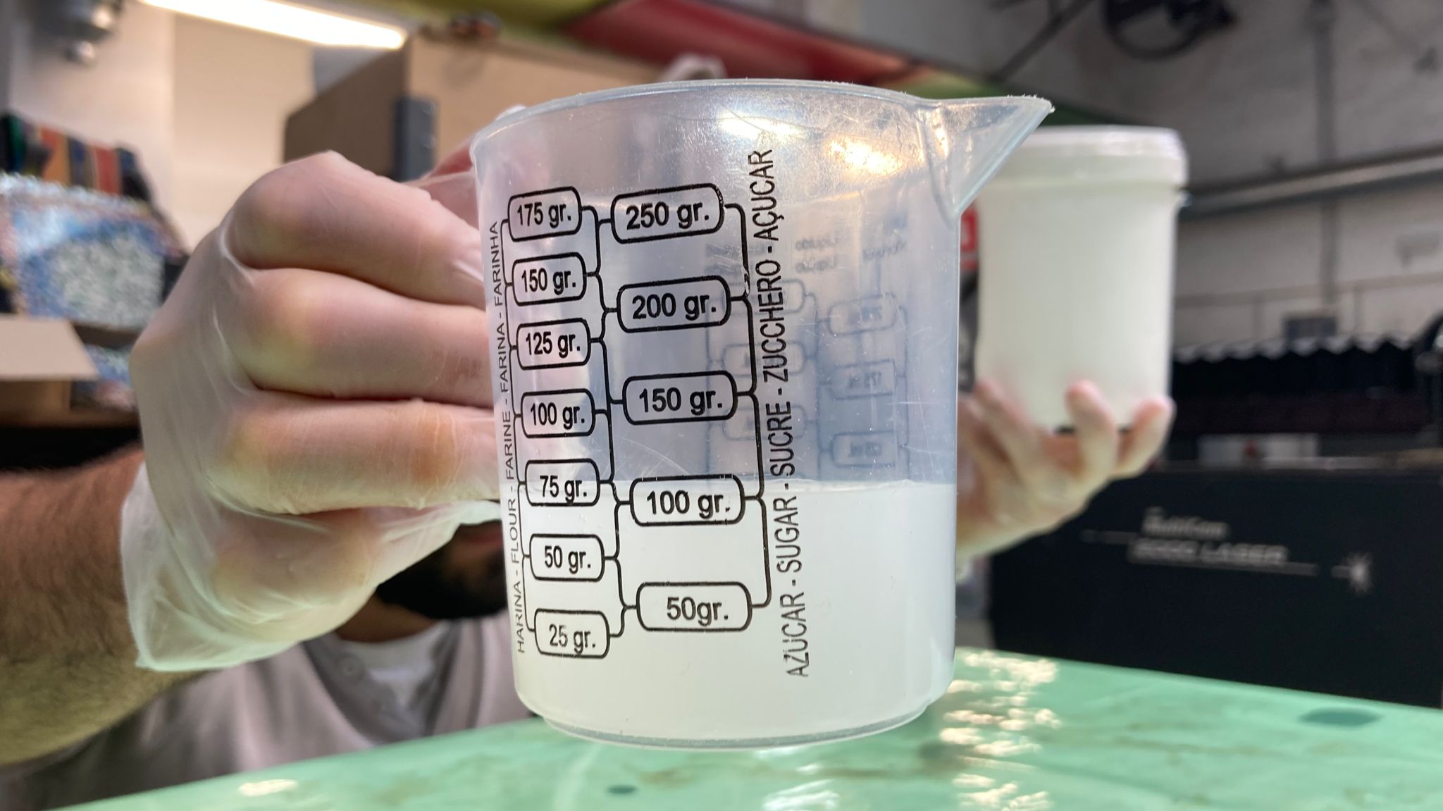
Once the first substance has been added, add the same amount of the other. Then mix. It will take a long time. And stir well in the corners and on all sides. And once we have it, we can pour it into the mould. But you have to go little by little, so as not to cause bubbles and so that the mould has less resistance.
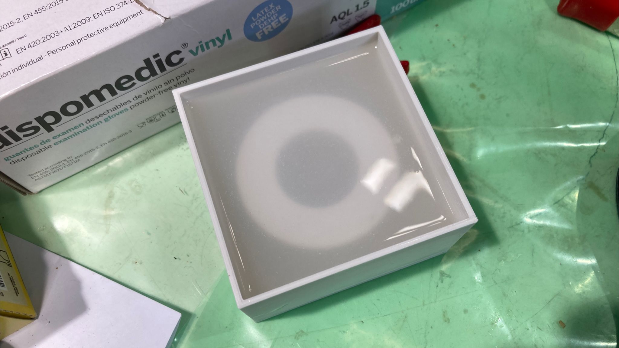
It should be left to rest for a couple of hours, in theory about 4 hours, but as the temperature, humidity and humidity change, this may vary. Once it has dried, we can carefully remove it.
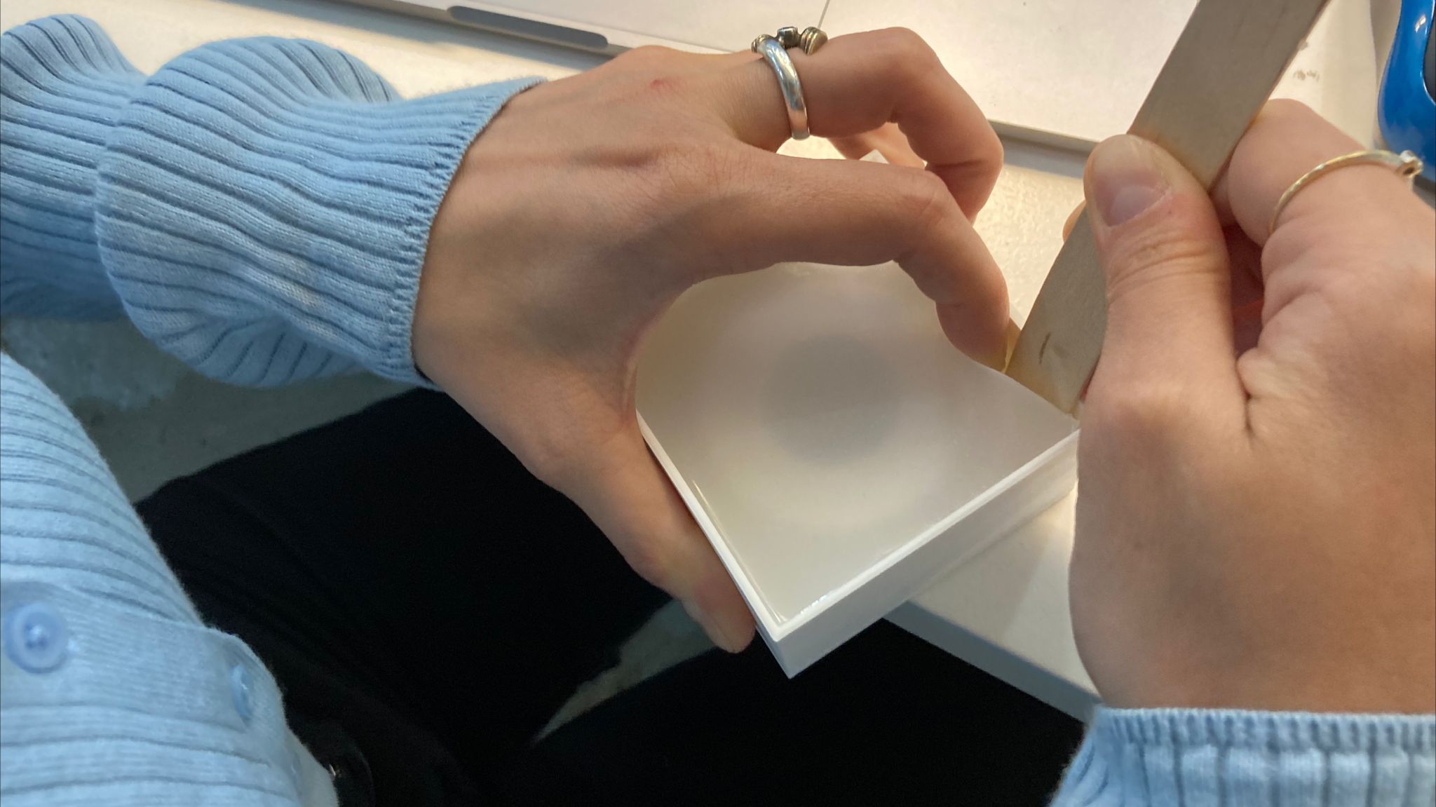
Active mold Final
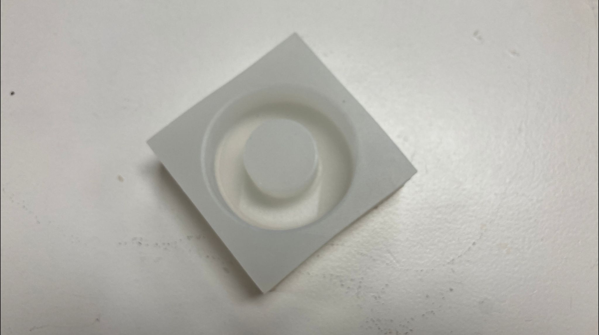
Final Design
W11_W13 - Inputs Outputs Devices
The weekly task:
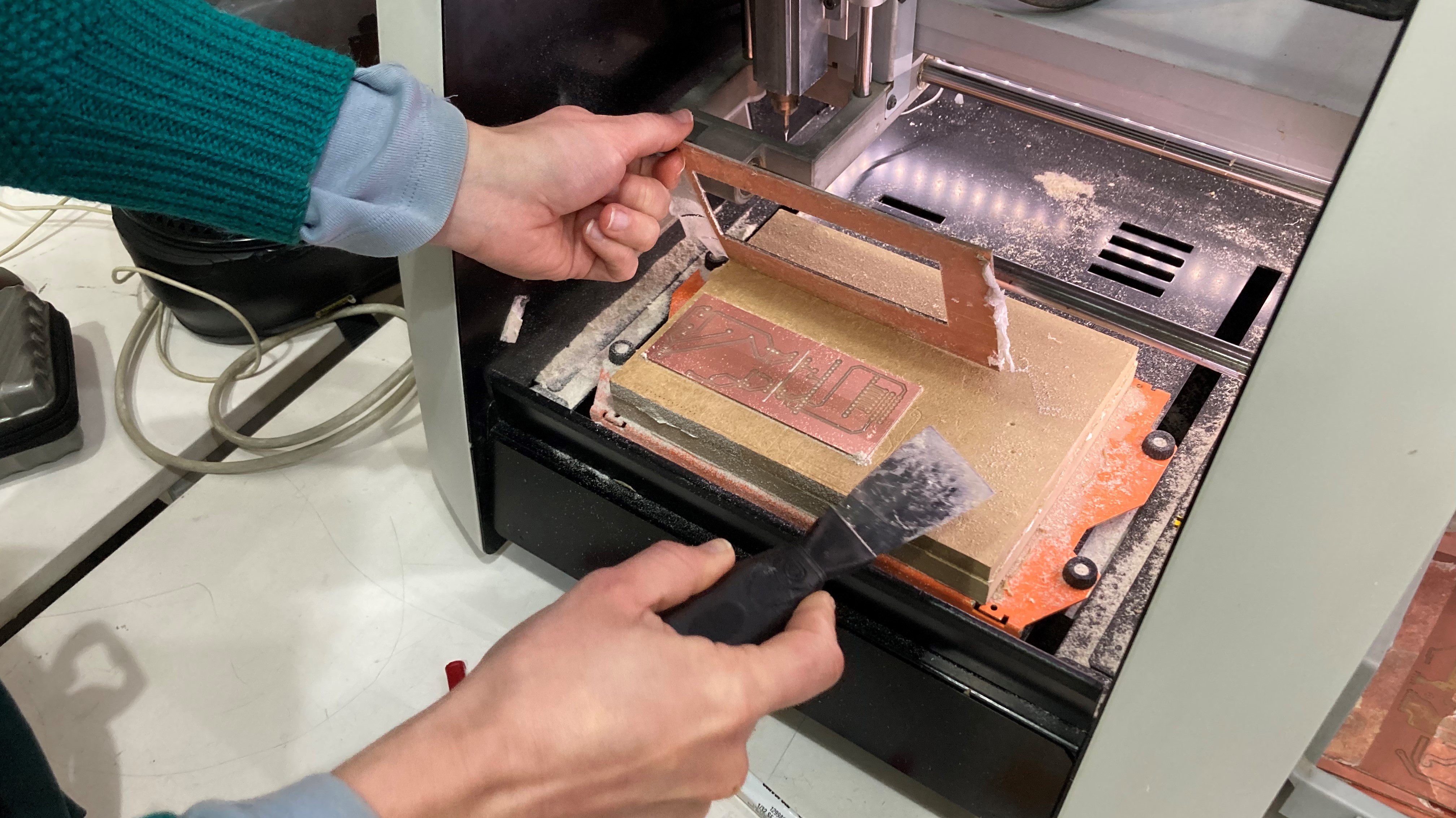
- You remember when you had to DESIGN A PCB for week 6? “design a pcb for an input or an output” now it is time to fabricate it ( finish the design - mill it - solder it)
- Make the PCB you designed real and make it work ( you have from these week until INPUT WEEK- included)
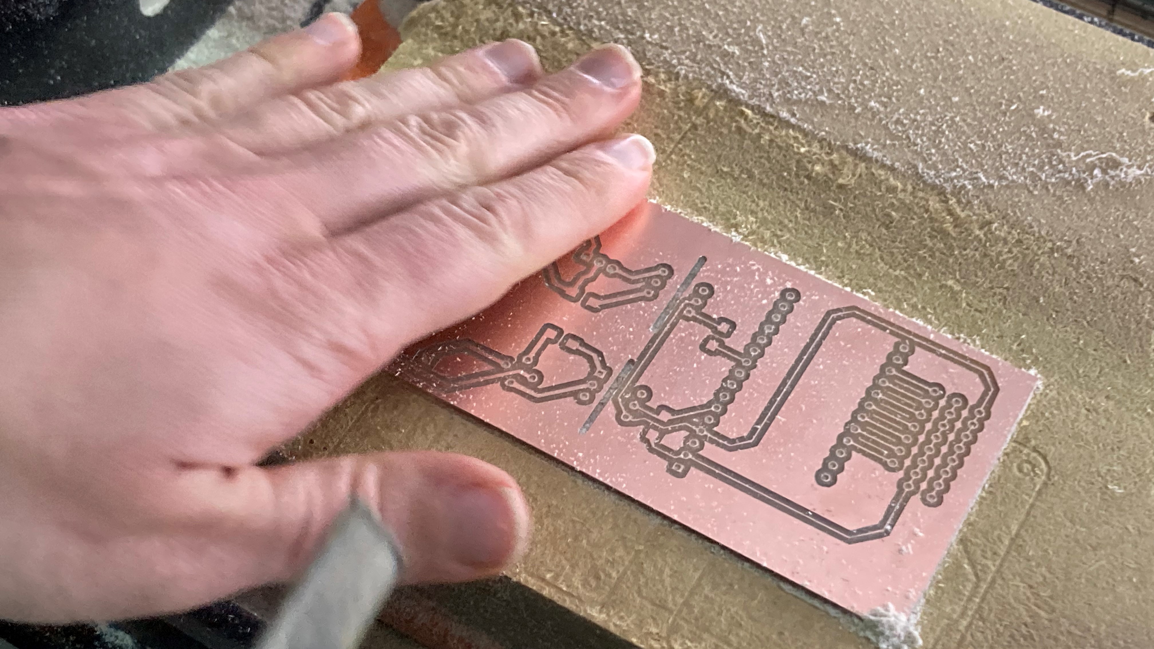
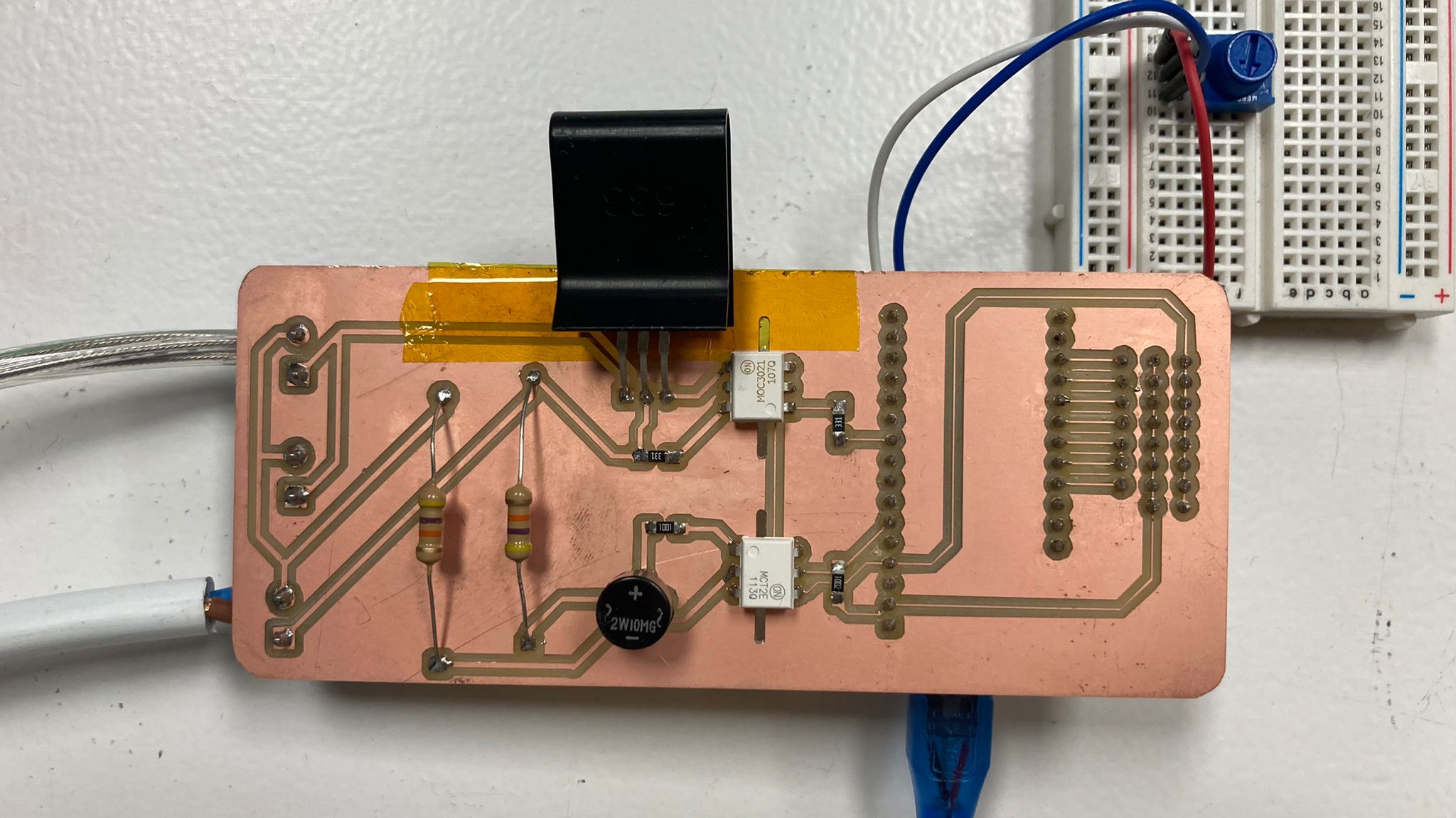
We created the pcb with Julia, so the work was done between the two of us. The idea is to create a board to control the temperature with the led lights, in order to create a dehydrator. First the board was printed after checking that everything was ok with Edu.
We had problems with the printing because the tip of the milling machine could not cut the copper completely. We assumed that this plate was curved and therefore from a certain point it did not have the same contact as at the edges. In the end we were lucky that they helped us to balance it in a different way than the staff had told us. We put the tip all the way in and then lowered it a bit more to give it speed. Finally it worked and we were able to print our plate correctly.
After the process we bought all the necessary electronics to be able to start soldering our motherboard. We check the addresses and positions of the elements, looking at the datasheets.
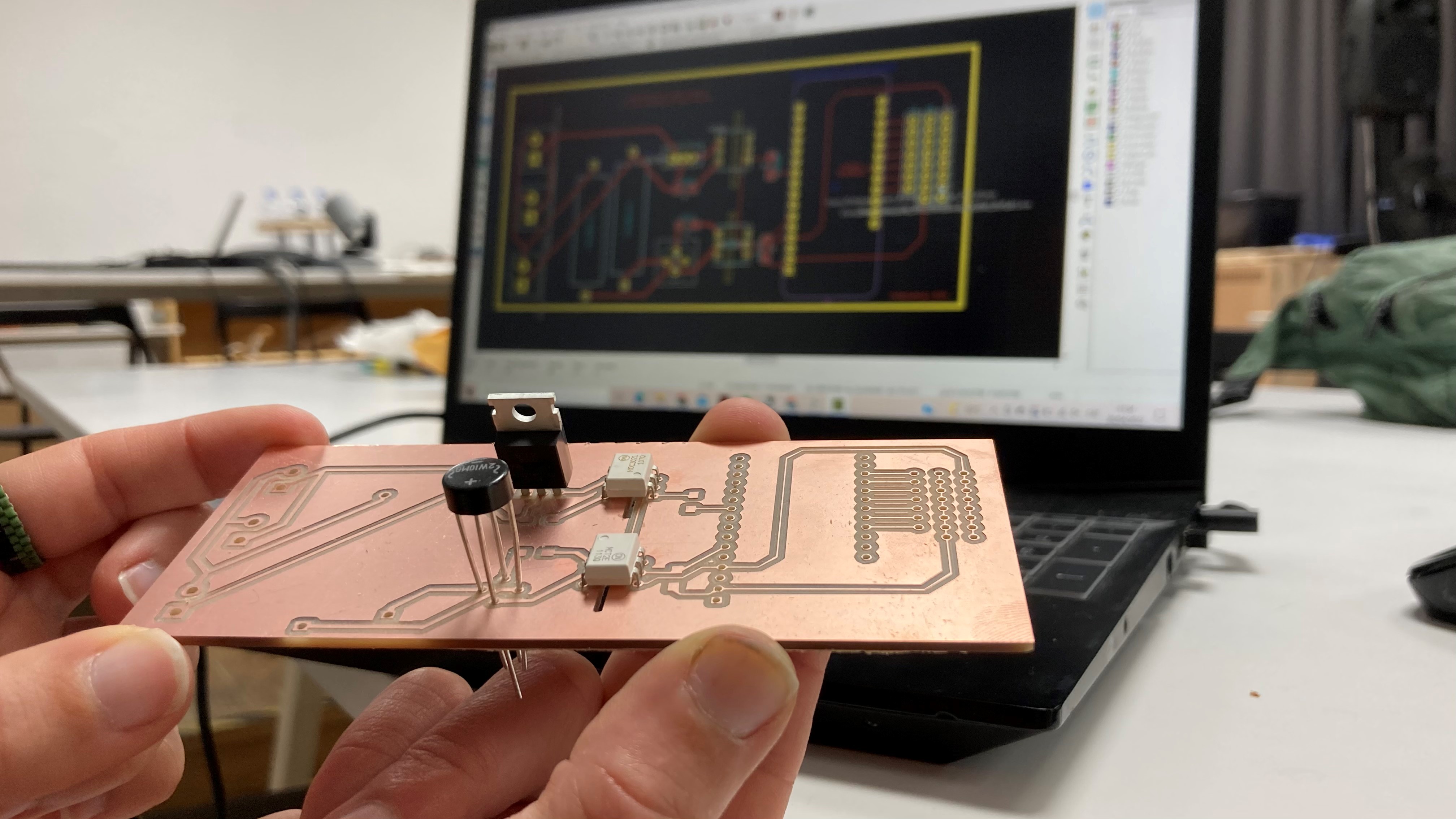
We started welding. To check that the soldering is correctly connected, every time we finish a soldering between elements, we check with the multimeter. If there is a short circuit, it means that the circuit is closed, and therefore the power is flowing between the solder joints.
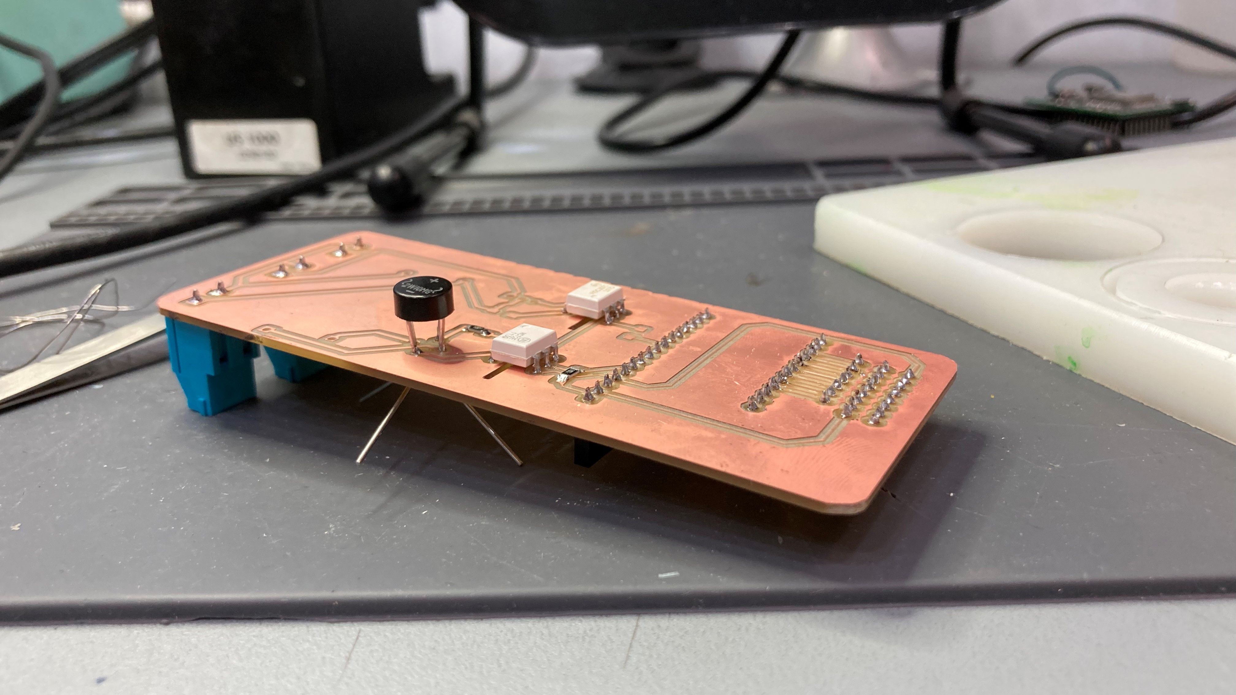
We were still missing some elements that FabLab didn't have and we were counting on them so we just bought them and continued soldering.
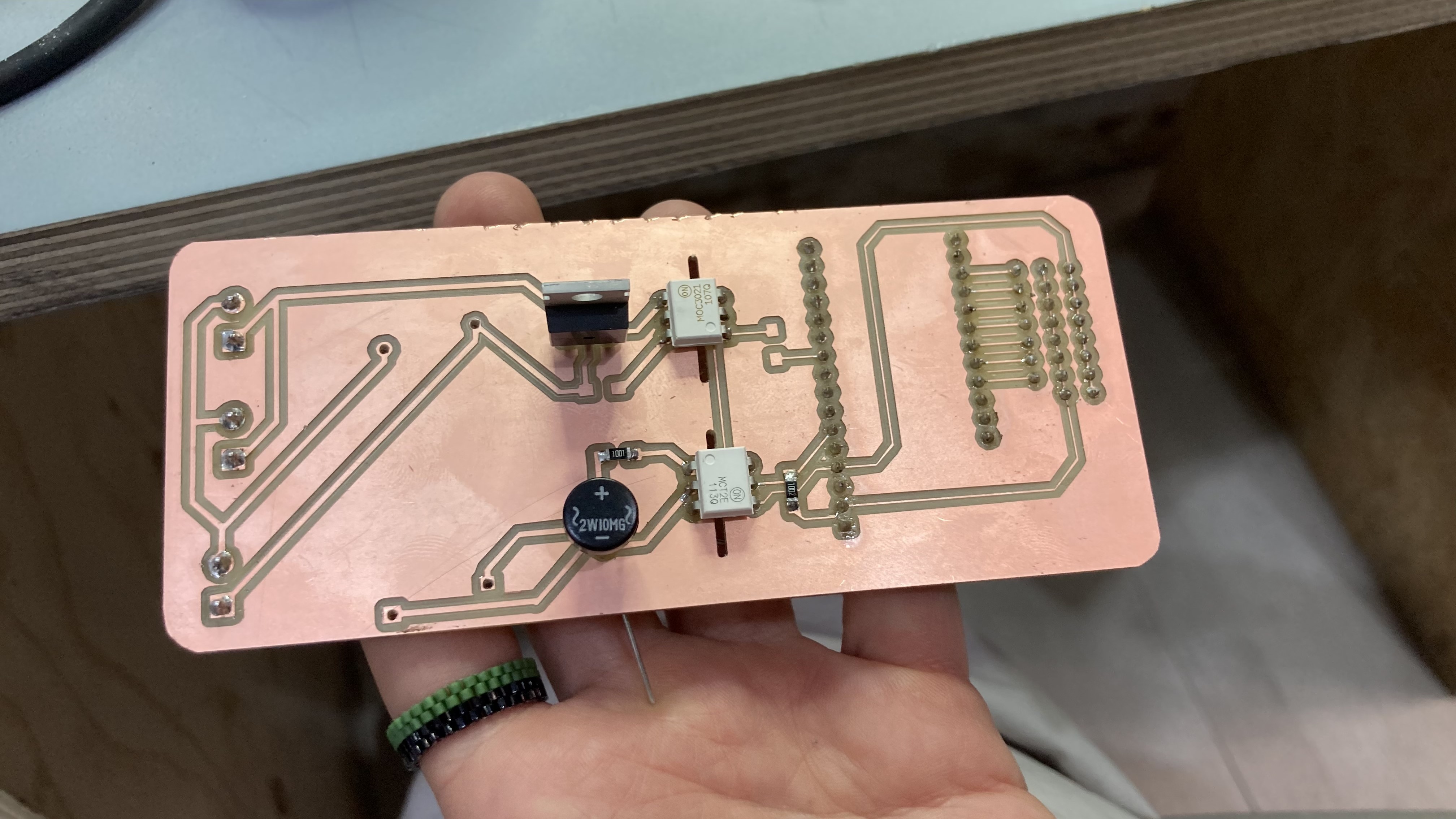
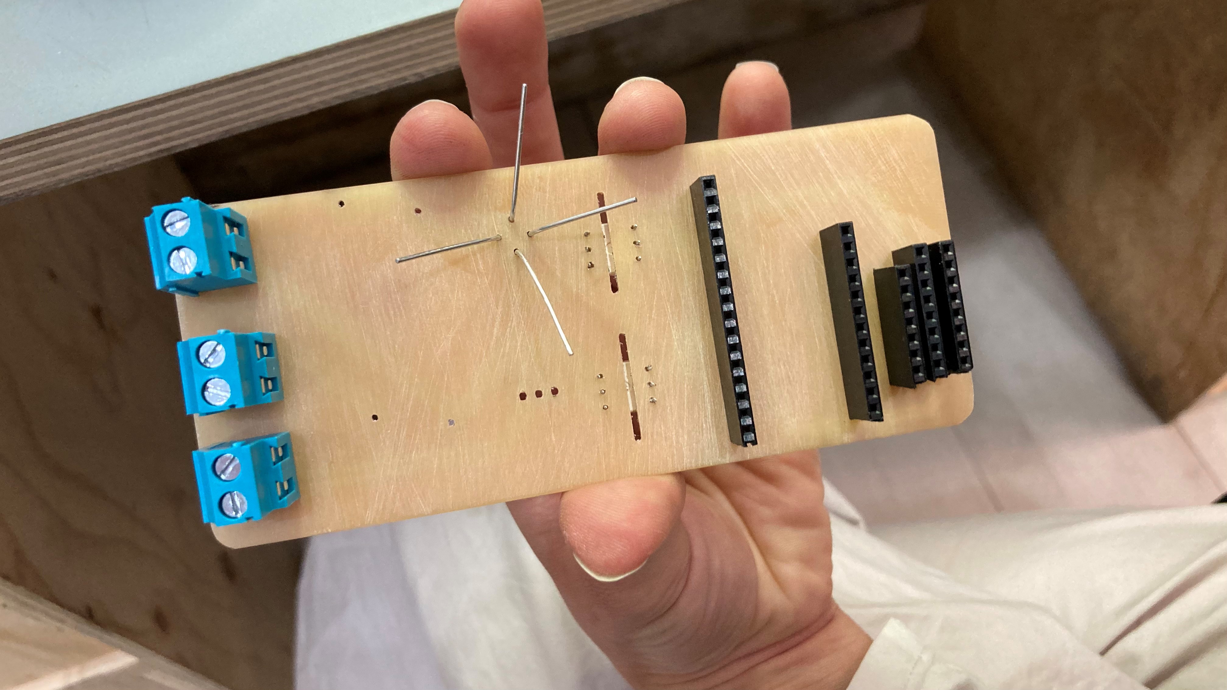
Final Design
W14 - Networking and communications
The weekly task:
- Send a message between two microcontrollers (boards/ esp32 feathers or boards you made). The task could be done by pairs
- Communication can be done by cable or wireless.
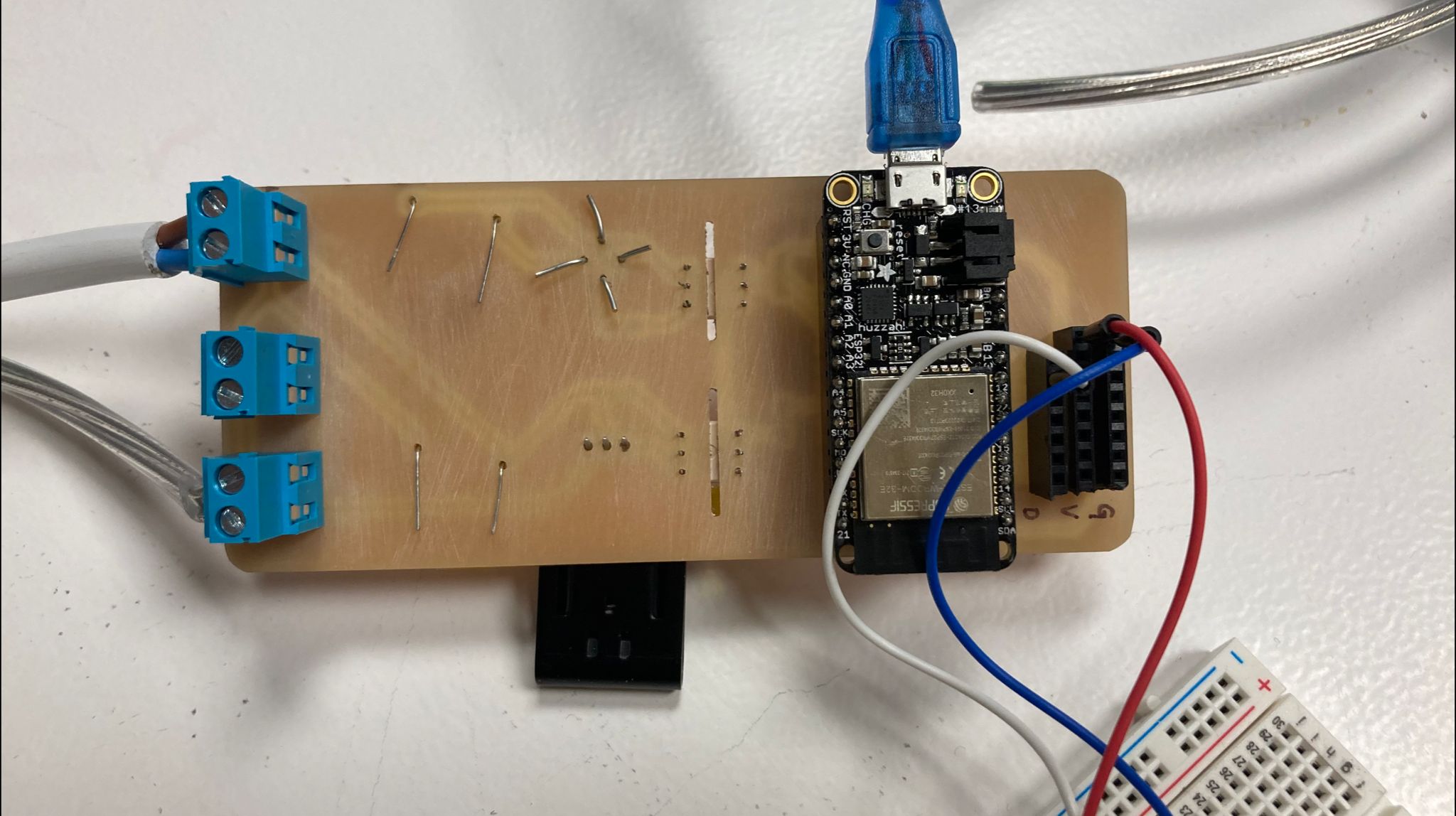
This task will be done with Kai, we are going to connect our two ESP32 with cables, and through the computer send a message from one to the other. To do this we will follow this tutorial.
This is the code we have used for each of the pcb.
void setup() {
Serial.begin(9600);
Serial1.begin(9600);
}
void loop() {
if (Serial1.available() > 0) {
char incomingByte = Serial1.read();
Serial.print (incomingByte);
}
if (Serial.available() > 0) {
char incomingByte = Serial.read();
Serial1.write(incomingByte);
}
}
W15 - Interface and application programming
The weekly task:
- Code/program an interface with the tools provided during the ( processing, P5JS, MitAppInventor, Aframe, NodeRed) or other alternatives software that interfaces a user with an input and/or output device that you want to use.
- Interpret and implement design and programming protocols to create a Graphic User Interface (GUI).
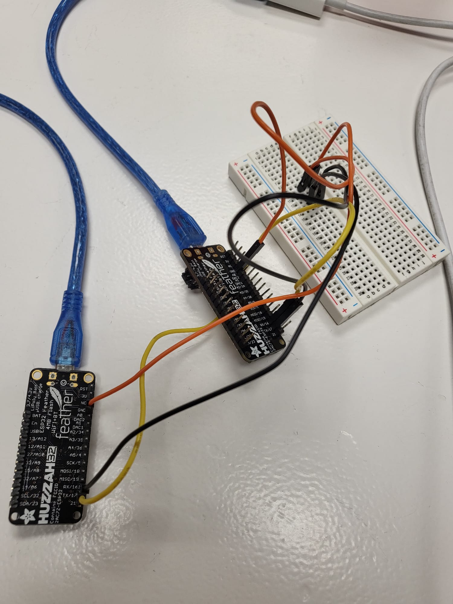
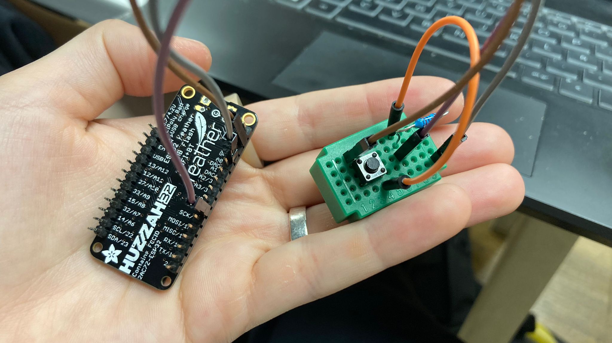
I am going to use the processing programme to be able to change the colour of a square from an output that would be the push of a button. I have followed a tutorial that is explained in the web page itself.
First of all, we create the connections between the elements and the pcb.
During the process when trying to implement the Processing code to the arduino it did not read the correct serial port and therefore did not apply the code. I got this error.
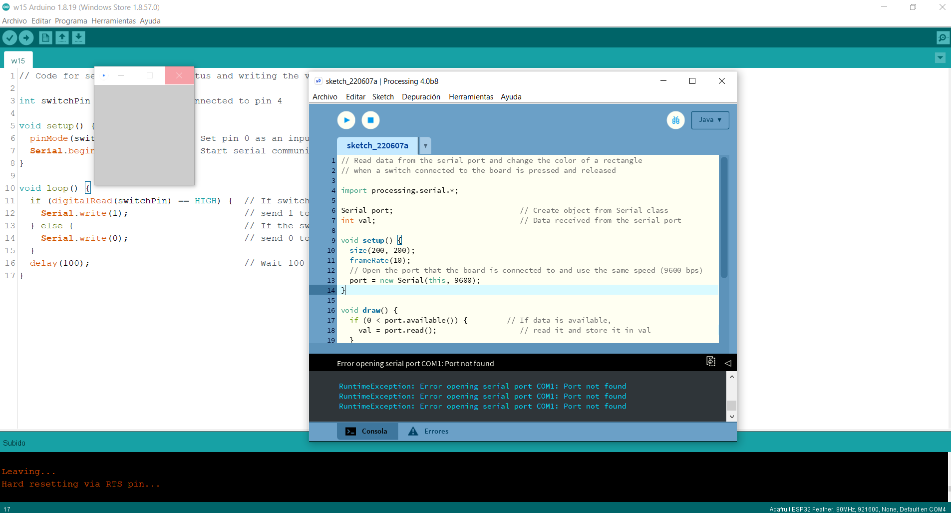
I used the following code to read the port on which it was connected, to check that it was not different from the Arduino one. And in the Processing console it printed COM4, which matched the Arduino one. But the program still searched for COM1.
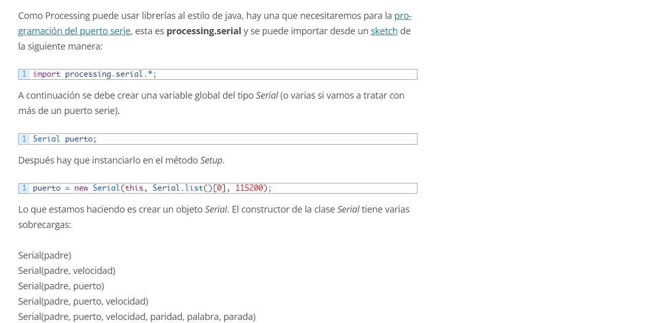
import processing.serial.*;
Serial myPort;
void setup(){
String portName[] = Serial.list();
println(portName);
}
Then on the internet looking how to call a port specifically in Processing, I found this web page, where I exposed the following. And I noticed that my code was missing the Serial.list( )[0] part, so I added it and it started working.
Final Code
Code for the Arduino
// Code for sensing a switch status and writing the value to the serial port
int switchPin = 4; // Switch connected to pin 4
void setup() {
pinMode(switchPin, INPUT); // Set pin 0 as an input
Serial.begin(9600); // Start serial communication at 9600 bps
}
void loop() {
if (digitalRead(switchPin) == HIGH) { // If switch is ON,
Serial.write(1); // send 1 to Processing
} else { // If the switch is not ON,
Serial.write(0); // send 0 to Processing
}
delay(100); // Wait 100 milliseconds
}
Code for the Processing
// Read data from the serial port and change the color of a rectangle
// when a switch connected to the board is pressed and released
import processing.serial.*;
Serial myPort; // Create object from Serial class
int val; // Data received from the serial port
void setup() {
size(200, 200);
frameRate(10);
// Open the port that the board is connected to and use the same speed (9600 bps)
myPort = new Serial(this, Serial.list()[0], 9600);
}
void draw() {
if (0 < myPort.available()) { // If data is available,
val = myPort.read(); // read it and store it in val
}
background(255); // Set background to white
if (val == 0) { // If the serial value is 0,
fill(0); // set fill to black
} else { // If the serial value is not 0,
fill(204); // set fill to light gray
}
rect(50, 50, 100, 100);
}
W16 - Wildcard Week
The weekly task:
- Design and produce something with a digital fabrication process (incorporating computer-aided design and manufacturing) not covered in another tasks
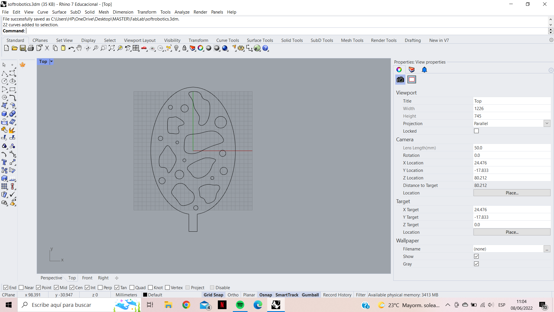
For this task I wanted to try making soft robotics with the vinyl and the baking paper. I think it might be interesting to explore other organic shapes with paper. And it is an activity that can be done at home very easily. First I have designed the organic shape that the paper and the vinyl will have with rhino.
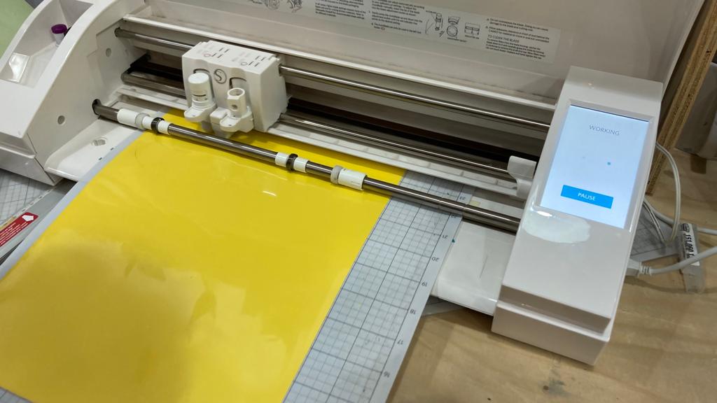
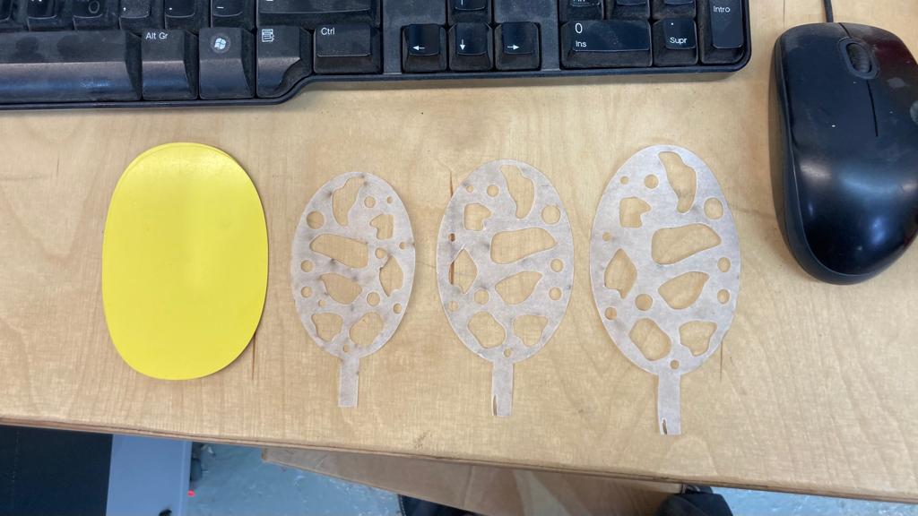
Then I cut out, with Daphne's help, two circles with Small-Vinyl Cutter - Cameo 3 the sticker vinyl. Then I wanted to cut the baking paper with this machine as well, but on Josep's recommendation, he said that it was much better to do it with the laser as the paper would not stick, which is the property we need, and it was very difficult to cut it with the Vinyl Cutter. I made different scales to check which one would best fit the shape of the vinyl.
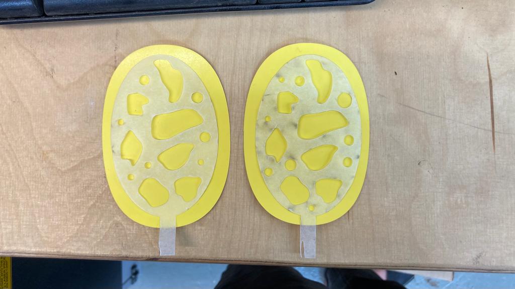
Afterwards, the plastic that surrounds the vinyl has been removed so that it has more elasticity. Then we put the three pieces together and ironed them.
Finally, a straw was inserted into the air inlet and blown out. We can see that the movement it provokes is more like ironing. But the interaction is fun.
W17 - Applications and implications
The weekly task:
- The main objective of this week is to begin focusing on your final projects and interventions, defining the scope and developing a project plan for the rest of the course. Some of the questions you should reflect on it and answer in your website:
Questions:
- What will it do?
It will be an interactive and collective platform, in order to create a space for creation and development to provide new opportunities for new generations. There will be a space where young designers will be able to show their games related to the theme. Another learning space with an online library where anyone can contribute knowledge. And finally the manifesto will focus on the main ideals.
- Who’s done what beforehand?
There are many websites with information on parenting and education. As well as repositories of DY games. But almost all of them are focused on "mothers", and heteronormative families. At the same time, everything is based on child care and learning, but there is no reflection on the relationships and roles that our behaviours and social culture impose on the new generations.
- What will you design?
To design the website and also construction games (most of them). To be able to understand that there are a lot more games than what is advertised and in the shops. In the graph below you can see more precisely all the designs and the following questions.
- What materials and components will be used?
In the case of the website nunjucks, json, html, javascript and css will be used. For the design of the games we want to use the most natural materials possible. That's why in this case we have; wood, 3D filament, wooden sticks, stones, agar-agar bioplastics, mycelium, textil.
- Where will it come from?
In the case of the website what is proposed is to use a template provided by Domestika. In the case of wood provided by Leroy Merlin. The wooden sticks and rocks will be taken directly from nature, in this case from the Pardines mountains and the Garraf coast. The filaments provided by FabLab. The textiles will be potato sack waste. The mycelium from grown bio.
- How much will they cost?
The total would be approximately 214,05€. Taking into account that there is a possibility that the mycelium set will not be produced due to its high cost, then the total cost of all the sets would be 115,05€.
- What parts and systems will be made?
Mainly what will be manufactured will be the shape and design of the product as the material itself will not have to be modified in terms of chemistry. Only in the case of the forest game will the material itself be created.
- What processes will be used?
The graph below shows the main manufacturing processes for each set. But the most commonly used are CNC, laser cutting and machining.
- What questions need to be answered?
The main concern is their resistance. Because in none of them has a monitoring of forces or mechanical resistance been carried out. They have been designed with the weight and safety of children in mind, but no calculations have been made. Now the question that made them create is the autonomy and the empowerment of the children over themselves, and the respect for their surroundings. Then the question is whether they will be useful in the present and in the future in terms of personal growth, and whether the purpose will be understood.
- How will it be evaluated?
First with adults and colleagues. To check for mistakes. And then with children.
W18 - Invention, intellectual property and income
The weekly task:
- Created a dissemination plan for your final project
- Outlined future possibilities and described how to make them probabilities
- Choose a licence (open/closed) of your choice for your final mdef intervention.
The main objective of the project is to make the site self-sufficient with input from the community, both families and educators as well as designers. To this end, a plan has been devised to make the website known and to promote it.
There are different possibilities for the evolution of the website. The first is that it develops well, the community grows well and there are no software problems. But it must be understood that the development of the website will always have to be improved. Another possibility would be an overload of information and having to cut the information or distribute it differently. It could also happen that no one collaborates in the project and it becomes stagnant in its evolution. Due to lack of attention and interest, both personal and collective.
The licence we would choose to run this project would be open source, with no personal data such as email addresses. This would be stored in a json web tokens document.
W1 - Principles and practices
The weekly task:
- Update your webpage with: A new section for FabAcademy, a post/page for each topic and a post/page for each Challenge
- Send a profile picture from you or anything represents yourself
- Browse through the fabacademy web pages of last year MDEF students, select 3 examples of documentation (from weekly tasks) that you find most interesting. Explain why and try to identify the key points.
To make the report I choose
Krzysztof Wronski,
Josefina Nano and
Roger Guilemany.
I have chosen these three websites because each one is a little different from the others in terms of presentation, but all three have in common that weekly separation, and not only thematic. As well as a chronological order. This makes the process of creation and personal development much more understandable
Krzysztof tells very well what he is working on and how he develops it, also his thoughts. As does Roger, who in a very honest way his hypotheses, facts and conclusions. Unlike Josefina, he arranges each week by Facts, Feelings, Findings and Future, making the work of reflection much more schematic, and as a consequence, practical.
Reflection
During the course of Designing for the Next Billion Seconds we were asked < WTF is internet? >, to which I responded:
It’s about a global connection of computers.
A billions of connections where you can find everything, as an implication of something.
I will say it is the algebraic image of computers in our lives, but maybe in the future it will be the metaverse.
A few years ago I thought about it. I realised that we systematically search the internet for what we want to know. So in my opinion, for humans, it's not just a way to connect, it's a way to escape and sometimes to reconnect with reality or to create other realities.
Also few years ago I made this video because of the idea that internet has become everything in our education system.
W2 - Computer-aided design
The weekly task:
- Design and create a 3d model with some relation to each person’s research project. The result must be uploaded to the website in a rendered format.
- Setting up context over the render of the 3D model using some 2D design software, the accounted context could be a poster that combines the render as collage or other 2D or 3D tools vectorial or raster compositions as you wish There should be some vectorial and raster drawings on the render.The modeling tools of use are completely open to your skills but we encourage you test softwares that you never used.”
For the 3D model I wanted to try with Rhino, because I already control Fusion, SolidEdge and NX. Also, I thought about Blender, but I see more future working with Rhino than Blender, as it is also a a software for animation even if you can use as an engineer.
I had some problems with Rhino, so for the next week I will try to work only with Rhino, but for now I did this model with Fusion.
The question of the beer it would be, What happens when we are not what we are suppose to be?
The idea not only came from Magritte, it's also a reflection of the shapes of cotidiant objects. As depending of the cultural, social and political sociology in the time.
This is the process:
W3 - Computer-controlled cutting
The weekly task:
- Create a small object using parametric design tools. The object should be assembled in a press-fit way (no use of glue, screws etc).
- Complete the Machine test with the 100% of the score
As you might expect, I had not used the laser cutter until I joined this master. Therefore, this is all new to me. As I said I forced myself to do the following task in rhino, to learn it. First I made a design of a piece of furniture as an easel in order to be able to engrave working processes from above. But when I finished I realised that the measurements were bigger than the piece of wood I had. So I designed a puzzle, as my focus of work is games and thinking.
The different types of processes to be implemented must be differentiated in the colours. The red will be engraving, the image and the text will be rastering as High, while the blue will be cutting. If cutting is done before engraving, the piece can move and become misaligned with the original design. Therefore the engraving will be done first and then the cut.
When opening the document in the rhino 5 of the computer connected to the laser, it only allows to choose the engraving or cutting mode, so even if it read the image as engraving, it did not transfer the information well. What we did with Josep then was to separate the file in two. First we printed the engraving without the cut. And then we printed the cut without the engraving. Thanks to the machine remembering the starting point, and obviously we didn't move the board.
MDF 3mm:
- Engrave - Raster : P(80) S(100) Hz(1000)
- Cut : P(55) S(0.5) Hz(1000)
I had some trouble separating some pieces because apparently the laser didn't cut the last layer of MDF, but otherwise there was no problem.
Although it is a great process of creation, it is obviously not made for a mass production process. For small parts it is perfect, but once you start working with large and detailed parts, you lose a lot of time. As well as the energy consumption and toxic fumes it produces. But in the end it is an essential tool for producing details.
I encourage you to create a new puzzle, personify it by changing the image (remember that in black and white the laser engrave much better).
Here you can find the files and download them.
:)
W4 - Electronics production
The weekly task:
- Finish (by pairs) your LED BADGE soldering the smd components and test it(make the led light up with the power supply)
- Tutorial reference
This practice consists of soldering 3 parallel lines 2 of 5 leds in series in each one and 1 line of 5 resistors. Once soldered, make them light up.
In order to weld correctly, you must first heat one of the areas where the element is to be welded with a little welding wire. The element is then positioned and welded on that side. And once we have it well caught, we solder the other side, thus finishing attaching the element to the plate.
With a multimeter we can check that the soldering is correct. By checking if the circuit is closed at each element between the solder joints, so that current is flowing.
By doing these checks I realised that the second LED soldered to the circuit I had put it in the wrong direction. And I noticed that the green line marked the direction of the LED.
I tried to remove the solder with the copper strip by heating it, as Julia explained to me that I could remove the solder wire. But I didn't know how to do it correctly. I thought it would be interesting to see how the leds are connected and see which ones were affected by this error. And this way I could see clearly how the board works.
Final Test
This was the result of the board being connected to a 5V supply, having the previous error.
We can see that only the LED that connects parallel to it is affected. And we can see how it is affected in parallel but not in series.
W5 - 3D printing and scanning
The weekly task:
- 3D print an object you have modelled(not something you have downloaded) that could only be made with Additive manufacturing techniques
- Your 3d printed object cannot be bigger than 70x70x70mm or take more than 3 hours
The printer I’ve decided to use to make the part is the creality LD-002H. This printer is resin, in this case Plant-based Elegoo translucent resin has been used. Rhino has been used together with Grasshopper to create the modeling. And the software for the machine has been chitubox.
The main idea of the object I would like to create is a version of the puzzle that contains two identical pieces and creates a pyramid between them. Since geometry is stipulated by the game itself, I would like to play with void and organic shapes.
Process
Since I had never used the GrassHopper tool I have looked for some tutorial to be able to make some dynamic form of my main idea. So I followed the following YouTube tutorial.
After creating the mesh, it has been saved in stl format and opened the chitubox program. As is the program recommended by the same company Creality, this already contains a library with different resin 3D printers. And since I’ve worked with this program before, it’s already programmed for the machine in question.
The process is basically to scale it as it seems perfect. Because it’s a design that only depends on the two pieces being the same, we don’t care so much about the exact size. And adding brackets to the piece. Being a piece with many holes and angles not very well if the machine will be able to correctly capture the shape, so and to facilitate its extraction without damaging the design, we must add supports (very rarely in resin is not necessary the supports).
From past experiences and as you can see it is obvious that once printed it will be very difficult to remove the supports. For this reason I have decided to print two parts with different support; one with support made automatically by the machine, and in the other I have manually removed the inner support. In this way we will be able to check if the part really needs the inner supports or not.
Final object
W6 - Electrincs design
The weekly task:
- Design a PCB board also called breakout-board for your ESP32 HUZZAH 32 microcontrollers ( or other board that you want to use rapberri pi ,etc) that allows you to connect an input (sensor) or an output (actuator) to your commercial board without cables.
- Include the design files in your webpage and explain well the process on how you did it.
For this activity we have learned to use kicad to be able to manufacture a pcb board. As Julia wants to create a dehydrator, which I am also very interested in, we have decided to do the activity together. Therefore we have created a PCB board with a temperature sensor and an AC drimmer necessary to change the intensity of the infrareds.
These are the resources we found on the internet. Thanks to this video, we were able to understand how AC drimmer worked and make one. In it you can find the necessary components to manufacture it and all the information of how it works.
During the process we needed Jeremy’s help, who really explained what we needed and how it worked. Also Daphne and Santi to be able to understand well the connections between the elements.
These are the components we need:
- 3x Terminal 2p 5
- 2x Resistor 47k
- Resistor 1k
- Resistor 10k
- 2x Resistor 330e
- Adafruit_Feather_HUZZAH32_ESP32
External resources library:
The Process
This is the scheme that Julia created with Jeremy, to understand what components we needed. Then we find the AC drimmer scheme, which for its high cost we decided to manufacture one instead of buying it, extracted from the previous video.
The tricky part is finding the parts needed to produce the dehydrator. After finding both symbols and footprint documents. But once this is all must be installed in the kidCad repository, the symbol in Schematic Layout Editor and the footprint in PCB Layout Editor. It must be understood that the symbology serves to make a diagram of the circuit, in terms of footprint, serves to create the real connections and paths between the components with their real measure.
Once the entire export process is done and we have the idea of the system we can start to create first the document Schematic Layout Editor, then generate netlist and with it open the PCB Layout Editor.
On Jeremy’s recommendation, the high volatge has been separated with the low, to avoid overloads.
Dehydrator AC drimmer PCB Board
First Prototype
Here you can find all the files of the first prototype.
W7 - Computer-Controlled Machining
The weekly task:
- Design something big IN PAIRS! . You can use up to a maximun of half full board ( that means 1200x1200mm) of the available material per student. 15 mm thick pine plywood boards.
For this practice I have decided to make some modular pieces. The intention is that children can create their own furniture when they play. For this reason it is necessary to fit and unfit the pieces together. So that children can play with them easily, but at the same time they can support the weight of a child. The dimensions of the pieces will be 330 mm, which is the average size of a seat for a 5 year old child.
Next, the thickness of the board (1200 x 1200 mm) has been measured, 14mm. Therefore a tolerance of 2mm has been left for the hole.
After converting the document with Borka and Angel, we started cutting the board together. On the Raptor X-SL Milling Machine it took 2 hours.
Once the process is finished, we have to remove the screws. And proceed to separate the pieces from the wooden panel. Once done, we can see that the surface finish of the wood, especially in the cut areas, is bad. This is why we must file, so as not to leave any wood chips that could hurt us.
Final Design
W8 - Embedded Programming
The weekly task:
- Use your programmer (HUZZAH32, ESP32 Feather) to program a circuit with a “led and a bottom” to do something
In order to start programming first you must make a flowchart. In this way we can understand the logical functioning that the computer will process. In my case, I want to program the random color change of the LED strip from a button.
This will be programmed with the arduino C++ language, using Arduino IDE, for our ESP32 Feather board.
#define PIN 15
#define NUMPIXELS 12
Adafruit_NeoPixel pixels = Adafruit_NeoPixel(NUMPIXELS, PIN, NEO_GRB + NEO_KHZ800);
int delayval = 250; // delay for half a second
int counter = 0;
int buttonPin = 3;
void setup()
{
Serial.begin(9600);
pixels.begin(); // This initializes the NeoPixel library.
randomSeed(analogRead(0));
pinMode(buttonPin, INPUT);
void loop()
{ if (digitalRead(buttonPin) == HIGH){
counter++;
if (counter == 1){
int led = random(12);
int redNumber = random(255);
}
if (counter = 2){
int led = random(12);
int greenNumber = random(255);
}
if (counter = 3){
int led = random(12);
int blueNumber = random(255);
}
if (counter = 4){
int redNumber = 0;
int greenNumber = 0;
int blueNumber = 0;
counter = 0;
}
pixels.setPixelColor(i, pixels.Color(redNumber,greenNumber,blueNumber));
pixels.show(); // This sends the updated pixel color to the hardware.
delay(delayval); // Delay for a period of time (in milliseconds).
}
W9 - Molding and casting
The weekly task:
- Make a mold (can be 1 or two sides) HARD-SOFT-HARD . 3DPRINT- CAST SILICONE- CAST SOMETHING INSIDE
- You can use biomaterials to substitute the silicone or the final cast.
The aim of this activity is to investigate the manufacturing processes of the biomaterial agar-agar. To this end, I have decided to create two active and two passive moulds in 3D printing. The passive one will be tested with the bioplastic to check if a rigid 3D filament mould can be used for its manufacture. While with the active one we will make another soft resin mould where we will test the same. Finally we will check the results with the 3D printing mould.
Process
First the two moulds have been designed in Rhino. Then they were left to print overnight on the Ender printer.
Passive mold
Having the mould in 3D we simply have to apply the recipe, which is based on:
- 4g Agar-agar
- 15mk Glycerin
- 80ml Water
It should be left to stand for at least 3 days in the mould, then removed and left to stand for 5 days.
Passive mold Final
Active mold
In this case we will use soft silicone. This way the proportion is 1/1. And it is much easier to make. Gloves and gown must be worn when dealing with the resin. As there were three of us who needed to make moulds, we decided to do it together.
First we calculate the volume we need, by putting the frills inside the 3D base and then measuring it. In my case I needed approximately 130ml. But as we were two more people we made a mixture of approximately 200ml in total.
Once the first substance has been added, add the same amount of the other. Then mix. It will take a long time. And stir well in the corners and on all sides. And once we have it, we can pour it into the mould. But you have to go little by little, so as not to cause bubbles and so that the mould has less resistance.
It should be left to rest for a couple of hours, in theory about 4 hours, but as the temperature, humidity and humidity change, this may vary. Once it has dried, we can carefully remove it.
Active mold Final
Final Design
W11_W13 - Inputs Outputs Devices
The weekly task:
- You remember when you had to DESIGN A PCB for week 6? “design a pcb for an input or an output” now it is time to fabricate it ( finish the design - mill it - solder it)
- Make the PCB you designed real and make it work ( you have from these week until INPUT WEEK- included)
We created the pcb with Julia, so the work was done between the two of us. The idea is to create a board to control the temperature with the led lights, in order to create a dehydrator. First the board was printed after checking that everything was ok with Edu.
We had problems with the printing because the tip of the milling machine could not cut the copper completely. We assumed that this plate was curved and therefore from a certain point it did not have the same contact as at the edges. In the end we were lucky that they helped us to balance it in a different way than the staff had told us. We put the tip all the way in and then lowered it a bit more to give it speed. Finally it worked and we were able to print our plate correctly.
After the process we bought all the necessary electronics to be able to start soldering our motherboard. We check the addresses and positions of the elements, looking at the datasheets.
We started welding. To check that the soldering is correctly connected, every time we finish a soldering between elements, we check with the multimeter. If there is a short circuit, it means that the circuit is closed, and therefore the power is flowing between the solder joints.
We were still missing some elements that FabLab didn't have and we were counting on them so we just bought them and continued soldering.
Final Design
W14 - Networking and communications
The weekly task:
- Send a message between two microcontrollers (boards/ esp32 feathers or boards you made). The task could be done by pairs
- Communication can be done by cable or wireless.
This task will be done with Kai, we are going to connect our two ESP32 with cables, and through the computer send a message from one to the other. To do this we will follow this tutorial.
This is the code we have used for each of the pcb.
void setup() {
Serial.begin(9600);
Serial1.begin(9600);
}
void loop() {
if (Serial1.available() > 0) {
char incomingByte = Serial1.read();
Serial.print (incomingByte);
}
if (Serial.available() > 0) {
char incomingByte = Serial.read();
Serial1.write(incomingByte);
}
}
W15 - Interface and application programming
The weekly task:
- Code/program an interface with the tools provided during the ( processing, P5JS, MitAppInventor, Aframe, NodeRed) or other alternatives software that interfaces a user with an input and/or output device that you want to use.
- Interpret and implement design and programming protocols to create a Graphic User Interface (GUI).
I am going to use the processing programme to be able to change the colour of a square from an output that would be the push of a button. I have followed a tutorial that is explained in the web page itself.
First of all, we create the connections between the elements and the pcb.
During the process when trying to implement the Processing code to the arduino it did not read the correct serial port and therefore did not apply the code. I got this error.
I used the following code to read the port on which it was connected, to check that it was not different from the Arduino one. And in the Processing console it printed COM4, which matched the Arduino one. But the program still searched for COM1.
Serial myPort;
void setup(){
String portName[] = Serial.list();
println(portName);
}
Then on the internet looking how to call a port specifically in Processing, I found this web page, where I exposed the following. And I noticed that my code was missing the Serial.list( )[0] part, so I added it and it started working.
Final Code
// Code for sensing a switch status and writing the value to the serial port
int switchPin = 4; // Switch connected to pin 4
void setup() {
pinMode(switchPin, INPUT); // Set pin 0 as an input
Serial.begin(9600); // Start serial communication at 9600 bps
}
void loop() {
if (digitalRead(switchPin) == HIGH) { // If switch is ON,
Serial.write(1); // send 1 to Processing
} else { // If the switch is not ON,
Serial.write(0); // send 0 to Processing
}
delay(100); // Wait 100 milliseconds
}
// Read data from the serial port and change the color of a rectangle
// when a switch connected to the board is pressed and released
import processing.serial.*;
Serial myPort; // Create object from Serial class
int val; // Data received from the serial port
void setup() {
size(200, 200);
frameRate(10);
// Open the port that the board is connected to and use the same speed (9600 bps)
myPort = new Serial(this, Serial.list()[0], 9600);
}
void draw() {
if (0 < myPort.available()) { // If data is available,
val = myPort.read(); // read it and store it in val
}
background(255); // Set background to white
if (val == 0) { // If the serial value is 0,
fill(0); // set fill to black
} else { // If the serial value is not 0,
fill(204); // set fill to light gray
}
rect(50, 50, 100, 100);
}
W16 - Wildcard Week
The weekly task:
- Design and produce something with a digital fabrication process (incorporating computer-aided design and manufacturing) not covered in another tasks
For this task I wanted to try making soft robotics with the vinyl and the baking paper. I think it might be interesting to explore other organic shapes with paper. And it is an activity that can be done at home very easily. First I have designed the organic shape that the paper and the vinyl will have with rhino.
Then I cut out, with Daphne's help, two circles with Small-Vinyl Cutter - Cameo 3 the sticker vinyl. Then I wanted to cut the baking paper with this machine as well, but on Josep's recommendation, he said that it was much better to do it with the laser as the paper would not stick, which is the property we need, and it was very difficult to cut it with the Vinyl Cutter. I made different scales to check which one would best fit the shape of the vinyl.
Afterwards, the plastic that surrounds the vinyl has been removed so that it has more elasticity. Then we put the three pieces together and ironed them.
Finally, a straw was inserted into the air inlet and blown out. We can see that the movement it provokes is more like ironing. But the interaction is fun.
W17 - Applications and implications
The weekly task:
- The main objective of this week is to begin focusing on your final projects and interventions, defining the scope and developing a project plan for the rest of the course. Some of the questions you should reflect on it and answer in your website:
Questions:
- What will it do?
- Who’s done what beforehand?
- What will you design?
- What materials and components will be used?
- Where will it come from?
- How much will they cost?
- What parts and systems will be made?
- What processes will be used?
- What questions need to be answered?
- How will it be evaluated?
It will be an interactive and collective platform, in order to create a space for creation and development to provide new opportunities for new generations. There will be a space where young designers will be able to show their games related to the theme. Another learning space with an online library where anyone can contribute knowledge. And finally the manifesto will focus on the main ideals.
There are many websites with information on parenting and education. As well as repositories of DY games. But almost all of them are focused on "mothers", and heteronormative families. At the same time, everything is based on child care and learning, but there is no reflection on the relationships and roles that our behaviours and social culture impose on the new generations.
To design the website and also construction games (most of them). To be able to understand that there are a lot more games than what is advertised and in the shops. In the graph below you can see more precisely all the designs and the following questions.
In the case of the website nunjucks, json, html, javascript and css will be used. For the design of the games we want to use the most natural materials possible. That's why in this case we have; wood, 3D filament, wooden sticks, stones, agar-agar bioplastics, mycelium, textil.
In the case of the website what is proposed is to use a template provided by Domestika. In the case of wood provided by Leroy Merlin. The wooden sticks and rocks will be taken directly from nature, in this case from the Pardines mountains and the Garraf coast. The filaments provided by FabLab. The textiles will be potato sack waste. The mycelium from grown bio.
The total would be approximately 214,05€. Taking into account that there is a possibility that the mycelium set will not be produced due to its high cost, then the total cost of all the sets would be 115,05€.
Mainly what will be manufactured will be the shape and design of the product as the material itself will not have to be modified in terms of chemistry. Only in the case of the forest game will the material itself be created.
The graph below shows the main manufacturing processes for each set. But the most commonly used are CNC, laser cutting and machining.
The main concern is their resistance. Because in none of them has a monitoring of forces or mechanical resistance been carried out. They have been designed with the weight and safety of children in mind, but no calculations have been made. Now the question that made them create is the autonomy and the empowerment of the children over themselves, and the respect for their surroundings. Then the question is whether they will be useful in the present and in the future in terms of personal growth, and whether the purpose will be understood.
First with adults and colleagues. To check for mistakes. And then with children.
W18 - Invention, intellectual property and income
The weekly task:
- Created a dissemination plan for your final project
- Outlined future possibilities and described how to make them probabilities
- Choose a licence (open/closed) of your choice for your final mdef intervention.
The main objective of the project is to make the site self-sufficient with input from the community, both families and educators as well as designers. To this end, a plan has been devised to make the website known and to promote it.
There are different possibilities for the evolution of the website. The first is that it develops well, the community grows well and there are no software problems. But it must be understood that the development of the website will always have to be improved. Another possibility would be an overload of information and having to cut the information or distribute it differently. It could also happen that no one collaborates in the project and it becomes stagnant in its evolution. Due to lack of attention and interest, both personal and collective.
The licence we would choose to run this project would be open source, with no personal data such as email addresses. This would be stored in a json web tokens document.